Troubleshooting
8-3
8.4
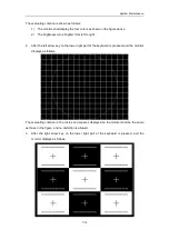
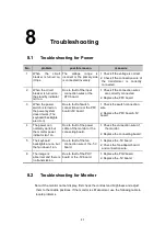
Troubleshooting for the Operation Process
No.
problem
possible reason
measure
1
There are minute dark
stripes in the near field.
1. Due to fault of the
transducer.
2. Due to fault of the
transmission circuit.
1. Replace the transducer.
2. Replace the transmission
board.
2
There are evident and
symmetrical dark areas in
the near field.
1. Due to fault of ADC.
2. Due to fault of
amplifier.
1. Replace the beamformer
board.
2. Replace the amplifier
board.
3
There are asymmetrical
dark areas in the near
field.
1. Due to fault of the
transmission board.
2. Due to fault of the
transducer board.
1. Replace the transmission
board.
2. Replace the transducer
board.
4
The image is displayed
with evident stripes,
flickers, bright spots or
dark spots.
1
.
Due to fault of the
digital circuit.
1. Execute self-diagnosis,
and
replace
the
corresponding board as
per error prompts.
2. If there is no error prompt,
replace boards in the
order of the beamformer
board and the DSP board.
8.5
Troubleshooting for Software
No.
problem
possible reason
measure
1
The HDD cannot be
recognized, since the
HDD indicator is always
on or off during start-up
process, rather than
flickers.
1
.
Due to CD drive,
the HDD is
affected.
2
.
Due to the HDD
fault.
1
.
Disconnect the CD cable of
the IO box.
2
.
Replace the HDD.
2
During the power-up
process, if the process
bar stops for a long time
(over 10s), the system
cannot normally be
entered.
1
.
Due to fault of
the HDD or CD
drive.
2
.
Due to error of
HDD preset data;
especially if the
preset data is
recently
changed.
3
.
Due to damage
of other data than
preset data of
HDD.
1
.
Refer to the first point
above.
2
.
Change the ”preset”
directory of C disk to another
name or directly delete it
(Doing this can make the
previously preset data
disabled, but can restore the
factory setups.)
3
.
Restore the system so as to
restore the factory setups.
Содержание DC-6
Страница 1: ...DC 6 DC 6T DC 6Vet Diagnostic Ultrasound System Service Manual...
Страница 2: ......
Страница 20: ...2 1 2 System Overview 2 1 System Appearance 2 1 1 Complete System with CRT Monitor...
Страница 23: ...System Overview 2 4 2 2 LCD Monitor...
Страница 26: ...System Overview 2 7 2 2 3 Lever of upper support arm...
Страница 66: ...4 1 4 System Structure and Assembly Disassembly 4 1 Exploded View of Complete System...
Страница 97: ...System Structure and Assembly Disassembly 4 32 10 screw caps 13 M4 8 screws Rear cover assembly...
Страница 101: ...System Structure and Assembly Disassembly 4 36 Power boards Card detacher...
Страница 138: ...Checks 6 4 6 3 Safety Checks 6 3 1 Electric safety Refer to Appendix D Electrical Safety Inspection...
Страница 187: ...D 13 ELECTRICAL SAFETY INSPECTION 7 Mains on Applied Part Leakage LIMITS For BF ECG Input and transducer 5000 A...
Страница 191: ...P N 2105 20 40473 V10 0...


