8-1
8
Troubleshooting
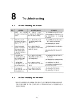
8.1
Troubleshooting for Power
No.
problem
possible reason
measure
1
When
the
circuit
breaker is turned on,
it trips.
The
voltage
range
is
incorrect or the primary side
is connected inversely.
1. Check if the voltage is correct.
2. Check if the connection wire of
the transformer is correctly
connected.
2
When the circuit
breaker is turned on,
the standby indicator
isn’t on.
Due to fault of the input
connection wires or the
PFC board.
1. Check if the connection wires
are correctly connected.
2. Replace the PFC board.
3
When the power
switch is turned on,
the power system
doesn’t work (The
keyboard backlights
aren’t on)
Due to fault of switch
connection wire or the PFC
board/+5V board.
1. Check the switch connection
wire.
2. Replace the PFC board/+5V
board.
4
The power can
normally work, but
the monitor power
indicator isn’t on.
Due to fault of the power
cable of the monitor or the
connecting board.
1. Check the connection wire of
the monitor.
2. Replace the connecting board.
5
The keyboard
backlights are on, but
the fan doesn’t run.
Due to fault of the fan
connection wire or the -5V
board.
1. Replace the -5V board.
2. Check the fan adapter board
and connection wire.
6
The image is
abnormal and there is
no transmission.
Due to fault of the PHV
board or the -5V board.
1. Replace the PHV board.
2. Replace the -5V board.
8.2
Troubleshooting for Monitor
Note: if the monitor cannot display, first check the contrast and brightness and adjust
them to the middle positions. If the monitor is still abnormal, use the following table to
locate problems.
Содержание DC-6
Страница 1: ...DC 6 DC 6T DC 6Vet Diagnostic Ultrasound System Service Manual...
Страница 2: ......
Страница 20: ...2 1 2 System Overview 2 1 System Appearance 2 1 1 Complete System with CRT Monitor...
Страница 23: ...System Overview 2 4 2 2 LCD Monitor...
Страница 26: ...System Overview 2 7 2 2 3 Lever of upper support arm...
Страница 66: ...4 1 4 System Structure and Assembly Disassembly 4 1 Exploded View of Complete System...
Страница 97: ...System Structure and Assembly Disassembly 4 32 10 screw caps 13 M4 8 screws Rear cover assembly...
Страница 101: ...System Structure and Assembly Disassembly 4 36 Power boards Card detacher...
Страница 138: ...Checks 6 4 6 3 Safety Checks 6 3 1 Electric safety Refer to Appendix D Electrical Safety Inspection...
Страница 187: ...D 13 ELECTRICAL SAFETY INSPECTION 7 Mains on Applied Part Leakage LIMITS For BF ECG Input and transducer 5000 A...
Страница 191: ...P N 2105 20 40473 V10 0...


