background image

System Structure and Assembly/Disassembly 

4-32 


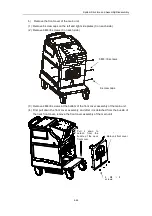
10 screw caps 

13  M4×8 
screws 

Rear cover assembly 

Содержание DC-6

Страница 1: ...DC 6 DC 6T DC 6Vet Diagnostic Ultrasound System Service Manual...

Страница 2: ......

Страница 3: ...of upper support arm 2 7 2 3 I O Panel 2 8 2 4 Power Panel 2 9 2 5 ECG Panel 2 10 2 6 Control Panel 2 11 2 6 1 Main panel 2 11 2 6 2 Minor panel 2 14 2 6 3 Keyboard 2 15 2 7 Symbols 2 18 3 Principle...

Страница 4: ...ing parts 4 9 4 3 4 Disassembly of the main panel 4 14 4 3 5 Disassembly of the minor panel 4 16 4 3 6 Replacement of the trackball 4 18 4 3 7 Replacement of the main panel PCBA 4 19 4 3 8 Replacement...

Страница 5: ...Schedule 6 1 6 1 2 Checks before inspection 6 1 6 2 Function checks 6 2 6 2 1 Flowchart for function checks 6 2 6 2 2 Content of the function checks 6 2 6 3 Safety Checks 6 4 6 3 1 Electric safety 6 4...

Страница 6: ...Power 8 1 8 2 Troubleshooting for Monitor 8 1 8 3 Troubleshooting for the Power up Process 8 2 8 4 Troubleshooting for the Operation Process 8 3 8 5 Troubleshooting for Software 8 3 8 6 Troubleshootin...

Страница 7: ...ray in China and other countries All other trademarks that appear in this manual are used only for informational or editorial purposes They are the property of their respective owners Responsibility o...

Страница 8: ...ect indirect or consequential damages or delay resulting from the improper use or application of the product or the use of parts or accessories not approved by Mindray or repairs by people other than...

Страница 9: ...number and a brief description of the reason for return 2 Freight policy The customer is responsible for freight charges when this product is shipped to Mindray for service this includes customs charg...

Страница 10: ...WARNING Indicates a potentially hazardous situation that if not avoided could result in death or serious injury CAUTION Indicates a potentially hazardous situation which if not avoided may result in...

Страница 11: ...stem to connect the printer Otherwise it may cause electric shock 2 Be sure to connect the potential equalization lead wire before inserting the equipment power plug into the receptacle Also be sure t...

Страница 12: ...ective there is risk of electric shock 9 Do not use the transducers other than those specified by Mindray Otherwise the equipment and the transducer may be damaged causing an accident such as a fire i...

Страница 13: ...ation manual does not describe clinical examination techniques Selection of the proper clinical examination technique must be based on specialized training and clinical experience 2 Malfunctions due t...

Страница 14: ...r water drops may be formed causing short circuit 7 If the circuit breaker is tripped it indicates that the machine or the peripheral devices have problems In these cases you cannot repair by yourself...

Страница 15: ...nect the system and its accessories such as printers or DVD recorder without turning OFF the power otherwise it may cause damage of the equipment or electric shock 12 Do not turn OFF the power supply...

Страница 16: ...direct sunlight 2 Locations subject to sudden changes in temperature 3 Dusty locations 4 Locations subject to vibration 5 Locations near heat generators 6 Locations with high humidity 4 Turn ON the s...

Страница 17: ...ithout consulting Mindray 11 Degradation of electrical and mechanical safety characteristics such as generation of a leakage current or deformation abrasion of mechanical parts and of image sensitivit...

Страница 18: ...mmable gasses 2 a CAUTION Do not place the system on a sloped surface Otherwise the system may slide unexpectedly resulting in person injury or the system malfunction The system should be moved over a...

Страница 19: ...rmance ICs are used to realize the front end transmission and reception and back end software functions the system is suitable for a wide variety of hospitals and clinics 1 2 Applicable Scope The DC 6...

Страница 20: ...2 1 2 System Overview 2 1 System Appearance 2 1 1 Complete System with CRT Monitor...

Страница 21: ...ng transducers and the main unit There are 3 active sockets and one dummy socket 8 Casters Used for fixing or moving the system 9 Handle Used for pushing the system 10 Transducer holder Used for placi...

Страница 22: ...No Name Function 1 Monitor Displays the images and parameters during scanning 2 Monitor support arm Supports and adjusts height and position of LCD monitor 3 Brightness buttons Adjust brightness of L...

Страница 23: ...System Overview 2 4 2 2 LCD Monitor...

Страница 24: ...1 and 2 are used to move the cursor up and down 3 is used as cancel and 4 is used as OK In the figure at the right side 1 and 2 are brightness adjusting buttons above which is a sun symbol A symbol ab...

Страница 25: ...p down adjustment of the monitor Note if there is no lever for another type of monitor you can adjust it directly The monitor can be tilted 20 degrees downward or upward See the figure below When the...

Страница 26: ...System Overview 2 7 2 2 3 Lever of upper support arm...

Страница 27: ...4 System reset 5 Serial port 6 Control port for color video printer 7 8 USB port 8 is used for USB devices while 7 is for expansion 9 10 Used for VGA I O 11 12 Used for RGB component video I O 13 14 U...

Страница 28: ...terminal Used for grounding connection 2 Equipotential terminal Used for equipotential connection 3 Power outlet Power supply for optional peripheral devices 4 Circuit breaker Used for cutting off pow...

Страница 29: ...nction 1 ECG lead signal input interface Used for connecting ECG leads and acquiring ECG signals 2 External ECG signal input port Used for connecting the signal output port of ECG monitor 3 Footswitch...

Страница 30: ...the PW mode 7 PW Steer Toggle to adjust SV steering angle of a linear transducer in the PW mode 8 Angle Toggle to adjust SV corrected angle in the PW mode 9 Scale Toggle to adjust pulse repetition fre...

Страница 31: ...creen display or changes the live image window in the Quad mode 27 Power Press to enter the Power Doppler mode rotate to adjust gain 28 Save Cine Quickly saves cine files to the default region of the...

Страница 32: ...n 43 Arrow Adds comment arrows and the arrow orientation is adjusted through the multifunction knob 44 Comment Press to start the comment function and the system enters the comment status 45 Report En...

Страница 33: ...uture use can be defined 5 Record Used for data recording can be defined 6 ECG Entering or exiting the ECG menu 7 iStation Entering the patient files management 8 Probe Switching between effective tra...

Страница 34: ...yboard inward slightly and then the keyboard automatically ejects outward At this time the light under the main control panel is bright automatically to lighten the keyboard Retraction of the keyboard...

Страница 35: ...ower case letters or upper and lower characters can be switched Shift Set 8 Ctrl Combined shortcut Ctrl Set 9 Alt Combined key 10 Pause Break 11 Home Moving the cursor to the head of the row or the le...

Страница 36: ...screen identical to the Report key 4 F4 Quickly starting the comment status identical to the Comment key 5 F5 6 F6 7 F7 8 F8 9 F9 Switching to the video replay menu 10 F10 Quickly starting preset func...

Страница 37: ...Type BF device Refer to relevant content in the Operation Manual to avoid safety accidents Dangerous voltage AC alternate current Functional earth Equipotentiality Protective earth Breaker ON OFF Pow...

Страница 38: ...System Overview 2 19 System reset Audio signal Microphone input jack Product serial number Manufacture date Manufacturer...

Страница 39: ...2 PHV2 A 5V A 5V A 12V D 3 3V D 5V D 12V A 5V A 5V D 5V D 3 3V D 5V D 3 3V D 12V A 5V A 5V POUT B M Front end FPGA configuration bus CW board Beamformer Front end control bus Scan control signal Scan...

Страница 40: ...the channel double pole double throw relays are respectively adopted to control the status of the transducer Now take relay drive of the transducer A as an example to describe the principle of the tr...

Страница 41: ...mission board is shown as follows The transmission board is designed for generation of high voltage pulse and transmission sequence The transmission circuit consists of two parts transmission sequence...

Страница 42: ...circuit consists of AD8132 and the peripheral circuits 3 2 4 Beamformer board The block diagram of the beamformer board is shown as follows The beamformer board consists of beamformer module signal pr...

Страница 43: ...ck diagram is shown as follows The Cine DSC 3D data capture and back end display modules are designed for post processing and the FPGA is adopted for these functions The MCF5474 is used as the system...

Страница 44: ...figuration for system FPGA and DSP System control parameter control for FPGA management for system controllers on line upgrading of each MCU 3 2 5 6 Connectors of the DSP board Connector Description S...

Страница 45: ...indicator D42 D44 ISP1583 Suspending status indicator D12 DSC FPGA configuration indicator D45 D48 Capture FPGA debugging status indicator D13 12V power indicator D49 Capture FPGA configuration statu...

Страница 46: ...orts footswitch Powered by power supply PC module Hard wired 1 1 serial port 3 USB ports S Video signal Status signal and PC power signal Powered by power supply USB microphone Soft wired 3 3 USB one...

Страница 47: ...ed in the front end of the reception circuit to isolate from the transducer if fault occurs for the relay control the high voltage may be applied to the front end of the reception circuit Therefore th...

Страница 48: ...is used as the built in PC The built in PC module consists of PC carry board industrial control board memory stick HDD and fan The PC carry board is introduced as follows The data transfer between the...

Страница 49: ...Principle Description 3 11 3 2 8 3 Interface definition The ZPACK110 socket is used for connecting the PC carry board and mother board and signals are defined as follows...

Страница 50: ...m PA SIG DES PB SIG DES PC SIG DES PD SIG DES PE SIG DES PA 1 GND PB 1 DM SIG PC 1 DP SIG PD 1 GND PE 1 VBUS SIG PA 2 GND PB 2 DM PC2 PC 2 DP PC2 PD 2 GND PE 2 VBUS PC2 PA 3 VBUS PC1 PB 3 DM PC1 PC 3...

Страница 51: ...other modules are in the broken lines LCD LCD 3 2 10 ECG module The ECG module is designed for monitoring of ECG signals and display of ECG waveforms which serve as reference of ultrasound images The...

Страница 52: ...S 2 data and they communicate with the main unit through serial ports The control panels and keyboard consist of main panel minor panel encoder panel and light control board etc The block diagram is s...

Страница 53: ...sing hardware which consists of CPLD and the peripheral circuit The trackball control circuit and encoder control circuit are used to convert the external mechanical actions to signals which are recog...

Страница 54: ...lowpass D5V ADT7516 CON1 CON2 CON3 CON4 SPI SPI voltage divider lowpass D3P3V clock JTAG SPI download interface 232 Max6066 VREF MAX3243 TTL CONNECTOR POWER D5V A5V 5V A5V REF3040 ADT7516_VREF voltag...

Страница 55: ...OSD board 1 6 15 inch LCD OSD connecting wire 1 7 15 inch LCD light board 12v 1 8 15 inch LCD power inverter board 1 9 15 inch LCD light switch and connecting wire 1 10 LCD fixing bracket 1 11 Reinfo...

Страница 56: ...erface board Speaker right Speaker left Key OSD board Toggle switch Audio R Audio L CCFL LVDS AC 90 260V VGA Audio L R Signal 12v 12v 12v 12v 3 2 14 3 Interface definition Definition of LVDS signal ou...

Страница 57: ...DBX 2 L SDBX 3 R SDBX 4 R SDBX Definition of VGA signal pins PIN NUMBER SIGNAL 1 VSYNC 2 GND 3 HSYNC 4 GND 5 RED 6 BLUE 7 GREEN 8 GND 9 GND 10 GND Definition of AC input pins PIN NUMBER SIGNAL 1 L 2 N...

Страница 58: ...through the BOOST PFC and then provided for the 5V board and 5V board to finally output 5V 3 3V 5V 12V and 12V The 12V serves as the input power of the PHV board and it passes the FLYBACK converter in...

Страница 59: ...CON 1 4 SW 5B ENA POFF LED GND 5V 3 3V A 12V 12V 5V HV PHV 1 4 SW ENA POFF LED GND 5B PF LED VCR isolation transformer LED indicator board Connecting board color video printer fan Fan connecting boar...

Страница 60: ...n the PFC boards sends the relay shut off signal and bypasses the thermistor rejecting surge current and the AC auxiliary output is switched on 3 3 2 2 PFC board The PFC board consists of APFC power c...

Страница 61: ...RCUIT DC VDD LED ENA SW RY PF POFF 5V BOARD 5V BOARD 3 3 2 3 5V board The structure of the 5V board is single end forward active clamp conversion The DC input voltage passes a LC filter and is sent to...

Страница 62: ...d adopts the structure of single end forward converter and its block diagram is shown as follows The 390Vdc input enters the power board through the 5V board and a connector and it passes the LC filte...

Страница 63: ...ter the 12V input voltage passes the BOOST converters and BUCK BOOST converters PHV1 PHV3 PHV2 and PHV4 are outputted The control IC of the FLYBACK converter is UC3843 made by ONSEMI and the main swit...

Страница 64: ...sive so it isn t necessary to describe it 3 4 System Software 3 4 1 Structure The system software consists of hardware interface layer medium support layer and upper software layer The upper software...

Страница 65: ...tware system runs through asynchronous processing mechanism of message control Commands are entered through GUI system and control panel and stored in mailboxes so that the software system can obtain...

Страница 66: ...4 1 4 System Structure and Assembly Disassembly 4 1 Exploded View of Complete System...

Страница 67: ...nit paddle assembly 8 2105 30 40437 minor panel rear cover assembly 24 2105 30 40359 main unit front cover assembly 9 2105 30 40386 minor panel assembly 25 2105 30 40373 video printer assembly optiona...

Страница 68: ...k of upper support arm gyration 11 2111 20 73285 Rubber cover 4 M6T 020002 Dish spring series 3 D 50 12 2111 20 73325 Damp axis 5 2111 20 73296 Washer of upper support arm gyration 13 2111 20 73288 Re...

Страница 69: ...itor 90 clockwise and remove the neck cable cover b Remove the cable clip disconnect the cables and take them out of the rear cover and neck cover c Assemble the neck cable cover and monitor tail cove...

Страница 70: ...embly put the cables inside the keyboard assembly and install the minor panel rear cover 4 3 1 2 Replacement of LCD monitor 1 Lock up the upper support arm Refer to Chapter 2 2 Remove the cable cover...

Страница 71: ...to tilt the monitor to the horizontal position refer to Chapter 2 3 Remove the wire strip screws and cable connector and remove the six screws fixing the monitor 4 To remove the LCD monitor from the...

Страница 72: ...he Monitor Test item b Press the left direction key on the minor keyboard to display the following screen Press 1 and 4 buttons and hold for at least 3s until the blue menu displays on the screen sele...

Страница 73: ...before you can select exit to leave the screen NOTE in autojust and autocolour tests the monitor captures the output signal of the product based on which to adjust the position and color of the monit...

Страница 74: ...machine as shown in the figure below b Remove two M3X8 countersunk screws to remove transparent cover c Remove the old lamp and replace it with new one 4 3 3 Replacement of spring damping parts 1 Lock...

Страница 75: ...rew pins and the M5 spring washers with a Philips screwdriver 5 Lift the support arm upward to the extreme position and then remove the two retainer rings at the end of the parallel bracket of the upp...

Страница 76: ...sure the upper support arm is turned upward to the extreme position before pushing the cross pin out 2 Hold the upper support arm when removing the cross pin in case the upper support arm falls off Ho...

Страница 77: ...he upper support arm along the pilot sleeve and extract the spring from the pilot sleeve 8 Remove the retaining nuts of the rubber damping pole and then remove the rubber damping pole from the end of...

Страница 78: ...the monitor stays still at a random height If not adjust the tightness of the spring by screwing the adjusting nut with a screwdriver until the monitor stays still at a random height and then fix the...

Страница 79: ...Remove the three holders on the right side of the main panel b Remove three M3x8 screws on the side of the main panel assembly and five M4x12 screws at the bottom The figure below doesn t show the ma...

Страница 80: ...nd Assembly Disassembly 4 15 c Draw out the handle of the main panel d Lift the front end of the main panel and disconnect the cables and take out the main panel Three M3X8 screws Five M4X12 screws Ma...

Страница 81: ...16 4 3 5 Disassembly of the minor panel a Remove the main panel assembly as per the procedures described in section 4 3 4 b Loosen the nondetachable screw and remove the minor panel rear cover assembl...

Страница 82: ...re before the operations above are performed otherwise the upper arm will interfere with the disassembly of the rear cover c Remove the two M4x8 screws fixing the sides of the minor panel assembly d R...

Страница 83: ...t out 4 3 6 Replacement of the trackball a Remove the main panel assembly as per the section 4 3 4 b Disconnect the cable of the trackball remove the fixing screws to take out the fixing bracket than...

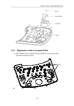
Страница 84: ...nd Assembly Disassembly 4 19 4 3 7 Replacement of the main panel PCBA 1 After the step 4 3 6 is completed and the trackball is removed pull out the knobs from the panel by hand Screw Fixing bracket Tr...

Страница 85: ...Structure and Assembly Disassembly 4 20 2 Turn over the main panel assembly loosen the fixing plate and fixing screws of encoders and remove the fixing plate and encoders Fixing screws Encode Fixing...

Страница 86: ...icone keys from the main panel PCBA a The silicone keys are installed in the main panel PCBA through the locating poles of the keys and the corresponding locating holes in the panel PCB and they can b...

Страница 87: ...nt of the keyboard PCBA a Remove the keyboard assembly as per the section 4 3 5 b Pull out eight STC DIP switches two encoder knobs and one double layer knob STC DIP switch Double layer knob Encoder k...

Страница 88: ...and take out the keyboard PCBA for replacement 4 3 9 Replacement of the keyboard Ejection and retraction of the keyboard assembly are both performed through pushing it inward a Push the keyboard assem...

Страница 89: ...o hands simultaneously to toggle the two plastic rods at the first nodes of the slide tracks on the back surface of the keyboard assembly squat down if necessary and slightly pull out the keyboard ass...

Страница 90: ...eyboard cable to the new keyboard assembly and tighten the screw on the keyboard connector clip f Hold the keyboard by hands align the tracks push the keyboard evenly to the end and repeatedly push an...

Страница 91: ...Replacement of the keyboard slide tracks a Remove the main panel assembly and minor panel assembly see section 4 2 3 and section 4 2 4 and disconnect the cables as shown in the figure below b Remove...

Страница 92: ...eatedly push the keyboard assembly to confirm that the keyboard can smoothly move and eject in position and tighten the four screws f According to the reversed order install the cast aluminum cover mi...

Страница 93: ...ent of the lock head a The procedures are identical to section 4 3 9 a b and c replacement of keyboard assembly b After removing the keyboard assembly remove the screws fixing the lock head 2 M3X8 scr...

Страница 94: ...tion 4 3 5 and remove the fixing screws of the cast aluminum cover to take out the cast aluminum cover b Remove two screws M2X10 cross panhead screw fixing the travel switch with cable replace it with...

Страница 95: ...ture and Assembly Disassembly 4 30 4 3 14 Disassembly of the system boards Layout of the system boards PFC board 5V board PHV board 5V board DSP board Beamformer board Transmission board CW board Ampl...

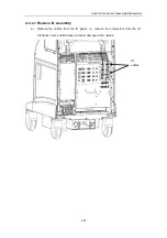
Страница 96: ...n it isn t necessary to move it 4 3 14 2 Remove the screw caps screws and rear cover a Remove 10 screw caps of the rear cover b Remove 13 M4 8 screws connecting the rear cover and the main unit housin...

Страница 97: ...System Structure and Assembly Disassembly 4 32 10 screw caps 13 M4 8 screws Rear cover assembly...

Страница 98: ...cture and Assembly Disassembly 4 33 4 3 14 3 Remove IO assembly a Remove the cables from the IO panel i e remove the connectors from the IO interfaces Care shall be taken to avoid damage of the cables...

Страница 99: ...g the IO assembly hold the two grips by hands and take out the IO assembly If a built in PC module is installed you shall disconnect USB and network cables between the PC module and IO assembly c Pull...

Страница 100: ...ables and shielding cover of the power main unit box disconnect the three power connectors of the auxiliary output assembly Remove six M3X8 screws fixing the shielding cover of the power box b Pull ou...

Страница 101: ...System Structure and Assembly Disassembly 4 36 Power boards Card detacher...

Страница 102: ...Repeat section 4 3 14 2 to remove screws and rear cover c Repeat steps a and b in section 4 3 14 3 to remove wires of IO panel and to remove IO panel remove the network cables and USB wire of PC modul...

Страница 103: ...er plate and bale of wire between 3D module and IO board f Disconnect the wire connector of the fan from the PC carry board remove the four M2 5X6 screws fixing the radiator and then remove the indust...

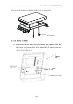
Страница 104: ...onnect wires from the PC carry board remove 8 M3X8 screws and take out the PC carry board i Disconnect the wires behind HDD remove four M3X8 screws fixing the bracket and remove the HDD M3X8 screws PC...

Страница 105: ...o replace HDD 4 3 16 Remove HDD a After removing the IO assembly disconnect the HDD power cable and signal cable then remove HDD bracket and 4 M3x8 screws fixing IO shielding cover and remove HDD and...

Страница 106: ...the HDD in its bracket to take out the HDD 4 3 17 Remove the DVD R W assembly a Remove the DVD R W cover Press down the two buckles on the CD RW cover and draw it out at an angle to take out the DVD R...

Страница 107: ...4 42 b Remove the DVD R W assembly 1 Remove the two M4 8 screws fixing the DVD R W assembly and main unit housing 2 Remove the DVD R W assembly and remove the power cable and signal cable 2 M4 8 scre...

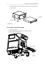
Страница 108: ...x8 screws at the bottom of the DVD R W to take out the DVD R W 4 3 18 Remove the ECG assembly a Remove the footplate 1 Remove 3 M4 8 screws at the bottom of the footplate assembly 2 Draw out the footp...

Страница 109: ...s 3 on each side 3 Remove 4 M4 8 screws at the bottom of the front cover assembly of the main unit 4 First pull down the front cover assembly and after it is detached from the buckle of the neck front...

Страница 110: ...move the cable of the ECG assembly d Remove 4 M4 8 screws of the ECG assembly pull it up until the ECG assembly is detached from the main unit housing and remove the ECG assembly M4X8 screw ECG assemb...

Страница 111: ...rew disconnect the cables and remove the ECG base assembly and ECG mounting cover f Remove M3X8 screws and replace the ECG board or footswitch connecting PCBA M3X8 screw ECG base assembly ECG mounting...

Страница 112: ...care shall be taken to avoid damage of interior connectors b Remove the shielding cover of the transducer board and aluminum shielding frames of the transducer sockets 1 Remove 19 M3x8 screws fixing t...

Страница 113: ...hielding frames and shielding plates of the transducer sockets and remove the shielding frames of the transducer 3 in total do not remove the pseudo transducer at the leftmost Shielding cover of the t...

Страница 114: ...nsducer mounting brackets 6 in total 4 Remove 12 M3x8 screws for the transducer board and shielding plates and separate the shielding plates and transducer board 4 3 20 Replace the inlet dust net a Lo...

Страница 115: ...the dust net support to the side until it is detached from the hook and take out the net support Loosen two nondetachable screws Inlet dust net Move the dust net support to the side Inlet dust net sup...

Страница 116: ...3 21 Remove the transformer a Remove the inlet dust net as per the step a in section 4 2 18 b Remove 4 M3x8 screws of the separating plate of the transformer and take out the separating plate c Remov...

Страница 117: ...nsformer and take out the transformer 4 3 22 Remove the fan assembly a Remove the inlet fan of the power main unit box 1 Remove the main unit rear cover 2 Remove 2 M3 8 screws of the inlet fan assembl...

Страница 118: ...8 screws of the inlet fan assembly 3 Hold the grips and draw out the outlet fan assembly c Remove the inlet fan of the system main unit housing 1 Remove the main unit rear cover 2 Remove 2 M3x8 screw...

Страница 119: ...sassembly 4 54 d Remove the outlet fan of the system main unit housing 1 Remove the main unit rear cover 2 Remove 2 screws fixing fan frame 3 Hold the grips and draw out the outlet fan assembly 2 scre...

Страница 120: ...r 100 kg in the mounting area of casters and lift the two casters at the same time thus the system doesn t topple to one side c Place a piece of wood in the middle of the front or rear bottom width 15...

Страница 121: ...e Put washers on the new casters and use a torque wrench to tighten the casters Torque 15 N m If the torque wrench isn t available apply a force of 75 N to the wrench in the position 20 cm away from...

Страница 122: ...ross panhead screws and 1 M4X8 cross panhead screws from the bracket Note the five screws mentioned above are all on the bracket of the printer for use 2 Use the 4 M3X8 cross panhead screws to fix the...

Страница 123: ...al cable reserved in the peripheral bay to the printer 4 Place the printer inside the peripheral space lift it slightly to grab it to avoid slippage of the printer and tighten the M4X8 screws for the...

Страница 124: ...olor printer The optional printers are of two models 1 Sony UP 20 2 MITSUBISHI CP 910E printer Note For the MITSUBISHI CP 910E printer set the parameter to ON via SERVICE MENU KEY SET MEM PRN 1 Remove...

Страница 125: ...move the fixing bracket 4 Open the plastic bag to take out the four M5 25 screws and install the mounting bracket on the system Note the side which has screw thread shall face to the left side of the...

Страница 126: ...Note that the side which has holes shall face to the front of the printer 6 Place the fixing bracket on the mounting bracket and push it inside the mounting bracket Note the guides of the fixing brac...

Страница 127: ...System Structure and Assembly Disassembly 4 62 7 Connect the signal cable and power cable Connection of signal cables of the color printer For REMOTE cable For S Video out cable For power cable...

Страница 128: ...Disassembly 4 63 4 4 3 Installation of VCR 1 First confirm the configuration of the VCR s DIP switches SONY SVO 9500MD 2 Remove the two side covers of VCR 1 2 3 4 5 6 ON OFF OFF OFF OFF ON OFF baud ra...

Страница 129: ...d Assembly Disassembly 4 64 3 Take out the VCR mounting bracket from the package and remove the screws fixed on the mounting bracket 4 Fix the VCR using four screws M4X8 screw M3X8 screw VCR mounting...

Страница 130: ...mbly 4 65 5 Push the VCR and bracket into the peripheral bay ensuring that the two elbows below the mounting bracket insert to the two bridges of the housing and the other side is fixed by two M4 8 sc...

Страница 131: ...ble to alternative of S VIDEO connectors The audio IN OUT and S VIDEO IN OUT cables are integrated into one strand of cables for the VCR module 7 Install the right cover but store the left cover prope...

Страница 132: ...nsducers Plastic bags 1 Approx 2 m 2 m 0 3 mm in thickness Vacuum cleaner 1 Blower 600W 16000 mm min 1 Makita 4014NV or equivalent Cleaner Brush 1 As small as a toothbrush Air spray or blower brush 1...

Страница 133: ...onfiguration of tools and consumables Tools list Tool Type Manufacturer Specifications standards Screwdriver various sizes and types Not specified Screwdriver various sizes and types Not specified Stu...

Страница 134: ...g material various types Not specified Screws nuts washers various types Not specified Solder Paper file various types Ethanol for cleaning and disinfection 5 2 Maintenance Personnel To ensure the per...

Страница 135: ...ature and humidity in the examination room The measurements related to electric safety are particularly sensitive to the humidity These measurements are also sensitive to the measuring location and me...

Страница 136: ...play modes can be normally switched Check that the transducers can be normally switched 6 2 Function checks 6 2 1 Flowchart for function checks Check the displayed time and date Check the initial oper...

Страница 137: ...down Check that the print key can normally work 5 Checking the trackball Pressing the Freeze key can enter the freeze status and pressing the Measure key can enter the measurement status Measure the...

Страница 138: ...Checks 6 4 6 3 Safety Checks 6 3 1 Electric safety Refer to Appendix D Electrical Safety Inspection...

Страница 139: ...ing mechanism of the monitor Check the fixation of the peripherals Check cable connection Check appearance of the transducers Check other mechanisms If the check result cannot pass it shows that the s...

Страница 140: ...that the control panel is free of looseness Push pull mechanism of the keyboard 1 Check the keyboard by eyes to confirm that its sliding tracks are free of deformation and crack 2 Check that the push...

Страница 141: ...se the wrench to check and confirm that the peripherals are free of looseness Cable connection 1 Check by eyes to confirm that the cables inside or outside the system are free of damage and scratch Ph...

Страница 142: ...the above checks for all transducers used 6 4 2 Check phantom data 6 4 2 1 Lateral axial resolutions 1 Smear ultrasound gel on the phantom and use the transducer to examine 2 After a good quality ima...

Страница 143: ...rm the above checks for each transducer 6 4 3 4 Check content 1 Checking functions Check the mode change measurements and relevant information 2 Checking image operations Perform image operations usin...

Страница 144: ...ripherals and accessories Clean the power cable and other cables 7 1 2 Content of the cleaning 1 Interior of the system and fan Unplug the power plug from the wall outlet Remove the accessories transd...

Страница 145: ...h off the dirt using neutral detergent 3 Monitor Check that the monitor is not skew and fixing mechanism is secured 4 Transducer Wipe off any dirt from the transducer check it for abnormalities such a...

Страница 146: ...t c Installing the trackball Put the rotary ball back in the trackball and then align the clamping ring click with the top cover notch Press the bulges on the ring with both hands and turn the ring ab...

Страница 147: ...Prior to software maintenance confirm that all relevant data must be those used in this system otherwise it may result in system damage At the same time the user shall back up the preset data as per t...

Страница 148: ...shown in the figure below 4 Click the OK button and the backup of preset data is completed 7 2 2 Restore the preset data After the software maintenance is completed the user must restore the preset d...

Страница 149: ...r onto Preset Data and select Load as shown in the figure below 3 After the Set key is pressed a dialog box appears select storage path and file as shown in the figure below 4 Click the OK button and...

Страница 150: ...7 2 3 1 Upgrade files in batches 1 Enter the preset menu via F10 on the keyboard as shown below 2 Select Maintenance and press the Set key after the dialog box below appears enter the password 3 Pres...

Страница 151: ...t key and then the system starts to upgrade files in batches 6 After the system prompts The upgrade is complete please turn it off and restart it to make the upgraded files effective the system finish...

Страница 152: ...System Maintenance 7 9 2 Move the cursor on the Upgrade item as shown in the figure below 3 Select the system software item and press the Set button as shown in the figure below...

Страница 153: ...after the upgrading of all files is completed will the system be restarted otherwise the system may not be initialized 7 2 4 System recovery When the system doesn t respond to any operation or cannot...

Страница 154: ...4 Follow the steps 1 through 3 in section 7 2 3 1 to enter the maintenance menu and select Config and press Set The Input Password dialog box appears 5 Input correct password and press OK to enter th...

Страница 155: ...2 5 Hard disk recovery If the hard disk is damaged or the system data is damaged please perform the following operations to recover Note You must confirm that the data of the hard disk recovery packa...

Страница 156: ...section 7 2 4 7 2 6 Install and uninstall the software of optional devices 1 Enter the Maintenance menu as per section 7 2 3 1 and click the option item and the Input Password dialog box appears as sh...

Страница 157: ...ialog box appears d Click OK button and the installation of DICOM is completed 4 Uninstall the DICOM e In the dialog box for installing and uninstalling the software select the Uninstall DICOM button...

Страница 158: ...correct KEY file to install the corresponding function software i In the dialog box for installing and uninstalling the software select Uninstall and corresponding function button and press the Set k...

Страница 159: ...to right 2 After the left arrow key on the lower right part of the keyboard is pressed and the monitor displays as follows The evaluating criterion is the circles and squares displayed on the monitor...

Страница 160: ...rs in the image area There are no three or more than three continuous dark points The sum of dark point defects is less than or equal to 7 and the number of dark points in the image area is less than...

Страница 161: ...log box of self diagnosis report appears 5 Press the Save button to save the self diagnosis report in the directory of D log if press the Cancel button the system will not save the self diagnosis repo...

Страница 162: ...e or the PFC board 5V board 1 Check the switch connection wire 2 Replace the PFC board 5V board 4 The power can normally work but the monitor power indicator isn t on Due to fault of the power cable o...

Страница 163: ...Troubleshooting for the Power up Process No problem possible reason measure 1 The power up graphic isn t displayed and there is no response from the system 1 Due to fault of the DSP board 2 Due to fa...

Страница 164: ...place the corresponding board as per error prompts 2 If there is no error prompt replace boards in the order of the beamformer board and the DSP board 8 5 Troubleshooting for Software No problem possi...

Страница 165: ...ls shall be used 2 Under Windows print a report to confirm that the printer can normally work 8 6 Troubleshooting for Others No problem possible reason measure 1 The fan cannot run 1 fault of 12V powe...

Страница 166: ...ult of the cable of the trackball 3 Fault of the trackball 1 Restart the system 2 Replace the cable of the trackball 3 Replace the trackball 7 There is no response from the keyboard 1 Fault of the sof...

Страница 167: ...er motherboard to output board 1 15 2105 20 40311 High voltage cable of power motherboard to output board 1 16 2105 30 40071 Digital signal processing board 1 System main unit housing assembly 2105 30...

Страница 168: ...e of CD RW module 1 48 2105 20 40284 Cable of VCR module 1 49 2105 20 40314 Power cable 1 of output board to system motherboard 1 50 2105 20 40317 Power cable 2 of output board to system motherboard 1...

Страница 169: ...nection cable 2 of transformer 1 69 2105 20 40291 AC input cable of connecting board 1 70 2105 20 40313 Output cable of connecting board to main unit 1 71 2105 20 40315 Ground line of line power suppl...

Страница 170: ...4 GND 5 GND 25 GND 6 GND 26 GND 7 VH1 27 5V2 8 GND 28 SW1 9 GND 29 GND 10 GND 30 GND 11 VH2 31 PW LED 12 GND 32 GND 13 GND 33 GND 14 GND 34 GND 15 VH2 35 NPW OFF 16 GND 36 GND 17 GND 37 GND 18 GND 38...

Страница 171: ...12 3 3V 6 3 3V 13 GND 7 GND 14 3 3V B 1 4 Definition of P10 interface between power output board connected to system motherboard Pin Definition Pin Definition 1 GND 7 A 5V 2 GND 8 GND 3 A 5V 9 A 5V 4...

Страница 172: ...face definition of IO interface board Interface Pin Definition J1 CD power interface 1 D5V 2 D5V 3 GND 4 GND 5 D12V 6 D12V 7 GND 8 GND J22 keyboard power interface 1 D5V 2 D5V 3 GND 4 GND 5 D12V 6 D12...

Страница 173: ...d Interface Interface definition of P4 main unit power P1 AC power input interface P2 transformer primary interface P3 transformer secondary interface P5 P6 AC auxiliary output interface Pin Definitio...

Страница 174: ...rum Color spectrum Preset MaintData DTA Maintenance data Current directory Dicom_Preset DTA PresetData DTA Current preset data generated automatically no need to copy Factory directory FactoryData DTA...

Страница 175: ...uipment These procedures assume the use of a 601PROXL International Safety Analyzer or equivalent safety analyzer Other popular testers complying with IEC 60601 1 used in Europe such as Fluke Metron o...

Страница 176: ...g body The Strain Relief No physical damage to the strain relief No plug warmth for device in use The Power Plug No loose connections The Power Cord The Power Cord No physical damage to the cord No de...

Страница 177: ...o meters switches connectors etc No residue of fluid spillage e g water coffee chemicals etc No loose or missing parts e g knobs dials terminals etc Contextual Inspection The Enclosure and Accessories...

Страница 178: ...N 3 Device Labeling TEST PROCEDURE Check the labels provided by the manufacturer or the healthcare facilities are present and legible Main Unit Label Integrated Warning Labels Slope and High Voltage C...

Страница 179: ...Y 3 2 Connect the test lead s between the RED input jack and the GREEN input jack 3 Press CAL LEADS The 601PRO will measure the lead resistance and if less than 0 150 Ohms it will store the reading an...

Страница 180: ...ance and current readings are taken This takes approximately 5 seconds 6 Press the print data key at any time to generate a printout of the latest measurement s Note When Over is displayed for Ohms th...

Страница 181: ...device internally TEST PROCEDURE Perform the Test 1 From the MAIN MENU or with the outlet unpowered plug the DUT into the 601PRO front panel outlet and turn on the device 2 Attach the device s applie...

Страница 182: ...deviations As a work around check the other outlets to see if they could be used instead Change another probe to confirm if the fail is caused by console Inspect wiring for bad crimps poor connections...

Страница 183: ...d parts correspond to the instrument type the applied parts will be tied together and one reading will be taken If any of the applied parts differ from the instrument type all applied parts will be te...

Страница 184: ...ace any defective part Inspect wiring for bad crimps poor connections or damage Test the wall outlet verify it is grounded and is free of other wiring abnormalities Notify the user or owner to correct...

Страница 185: ...EY 2 1 Disconnect ALL patient leads test leads and DUT outlet connections 2 Press CAL to begin calibration as shown If the calibration fails the previously stored readings will be used until a passing...

Страница 186: ...ly Failure Check any broken of the AC DC adapter and its cable Replace a new one if any portion defective Check any broken of the enclosure Replace any defective part Inspect wiring for bad crimps poo...

Страница 187: ...D 13 ELECTRICAL SAFETY INSPECTION 7 Mains on Applied Part Leakage LIMITS For BF ECG Input and transducer 5000 A...

Страница 188: ...e Lead Types from the View Settings Option refer to Lead Type Definitions in Section 5 of this chapter 4 Press shortcut key 8 The Patient Auxiliary Current test is displayed and the test begins immedi...

Страница 189: ...Test the wall outlet verify it is grounded and is free of other wiring abnormalities Notify the user or owner to correct any deviations As a work around check the other outlets to see if they could be...

Страница 190: ...osure and Accessories 3 Device Labeling 4 Protective Earth Resistance Max 0 2 5 Earth Leakage Normal condition NC ____ A Max NC 300 A refer to UL60601 1 NC 500 A refer to IEC60601 1 SFC 1000 A Single...

Страница 191: ...P N 2105 20 40473 V10 0...

Отзывы: