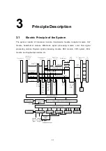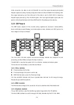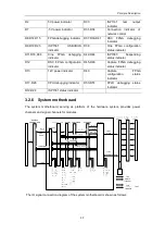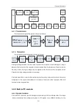
Principle Description
3-6
The USB interface HDD can be realized.
3.2.5.4
Display module
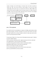
Processing of graphic and image integration and provision of control interface for main
CPU to graphic memory
The graphic memory is directly accessed by CPU.
Interface control of video input and output
3.2.5.5
CPU system
The CPU system is the control core of the ultrasound system, consisting of hardware
system and software system. The hardware provides support for functions of the system
software, and the software realizes the control of hardware modules. The functions of the
CPU system include: image display and measurements, and human-machine interaction.
Communicating with other MCU or DSP, and configuring, initializing, and monitoring each
hardware module;
Initialization configuration for system FPGA and DSP;
System control: parameter control for FPGA; management for system controllers; on-line
upgrading of each MCU.
3.2.5.6
Connectors of the DSP board
Connector Description
Status
Remarks
J1
USB IDE HDD interface
Not supported
J2
Reserved FPGA serial port
Not welded
J4
Reserved 1561 USB Host port
Not supported
J6
CPU BDM and JTAG select
jumper
No jumper for
BDM
J7
Small HDD socket
Not supported
Either HDD socket or CF
socket is welded
J10
JTAG link of PLD
Supported
For JTAG configuration of
CPLD and FPGA
J11
JTAG link of CPU and PLD
Not supported
J14
USB Device interface of CPU
Not supported
J15
BDM socket interface of CPU
Supported
For CPU system debugging
and program downloading
J166
CF card socket
Not supported
JP1-4
Used for connecting CPU’s
JTAG link and PLD’s JTAG
link
Not supported
3.2.5.7
Functions of LED indicators
Connector
Description
Connector
Description
D1
3.3V power indicator
D27
FPGA
configuration
indicator
Содержание DC-6
Страница 1: ...DC 6 DC 6T DC 6Vet Diagnostic Ultrasound System Service Manual...
Страница 2: ......
Страница 20: ...2 1 2 System Overview 2 1 System Appearance 2 1 1 Complete System with CRT Monitor...
Страница 23: ...System Overview 2 4 2 2 LCD Monitor...
Страница 26: ...System Overview 2 7 2 2 3 Lever of upper support arm...
Страница 66: ...4 1 4 System Structure and Assembly Disassembly 4 1 Exploded View of Complete System...
Страница 97: ...System Structure and Assembly Disassembly 4 32 10 screw caps 13 M4 8 screws Rear cover assembly...
Страница 101: ...System Structure and Assembly Disassembly 4 36 Power boards Card detacher...
Страница 138: ...Checks 6 4 6 3 Safety Checks 6 3 1 Electric safety Refer to Appendix D Electrical Safety Inspection...
Страница 187: ...D 13 ELECTRICAL SAFETY INSPECTION 7 Mains on Applied Part Leakage LIMITS For BF ECG Input and transducer 5000 A...
Страница 191: ...P N 2105 20 40473 V10 0...

