Principle Description
3-24
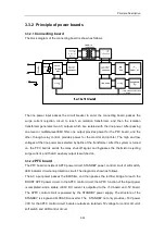
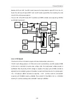
PFC
board
Input
filter
FORWARD
converter
secondary
auxiliary power
supply
+5V/30A
output
+3.3V/30A
output
PWM
control
feedback
+5V/+3.3V
BUCK
converter
PF signal
circuit
optocoupler
isolation
(feedback)
optocoupler
isolation
(feedback)
Active
clamp
PF signal
3.3.2.4
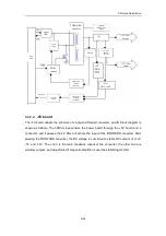
-5V board
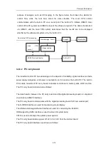
The -5V board adopts the structure of single-end forward converter, and its block diagram is
shown as follows. The 390Vdc input enters the power board through the +5V board and a
connector, and it passes the LC filter to become the input of the FORWARD converter. After
passing the FORWARD converter, the DC voltage is converted to stable DC outputs of +12V,
-5V and -12V. The +12V is the main feedback output of the converter, the other two are
auxiliary outputs, and adjustment of magnetic amplifier is used as stabilizing method.
Содержание DC-6
Страница 1: ...DC 6 DC 6T DC 6Vet Diagnostic Ultrasound System Service Manual...
Страница 2: ......
Страница 20: ...2 1 2 System Overview 2 1 System Appearance 2 1 1 Complete System with CRT Monitor...
Страница 23: ...System Overview 2 4 2 2 LCD Monitor...
Страница 26: ...System Overview 2 7 2 2 3 Lever of upper support arm...
Страница 66: ...4 1 4 System Structure and Assembly Disassembly 4 1 Exploded View of Complete System...
Страница 97: ...System Structure and Assembly Disassembly 4 32 10 screw caps 13 M4 8 screws Rear cover assembly...
Страница 101: ...System Structure and Assembly Disassembly 4 36 Power boards Card detacher...
Страница 138: ...Checks 6 4 6 3 Safety Checks 6 3 1 Electric safety Refer to Appendix D Electrical Safety Inspection...
Страница 187: ...D 13 ELECTRICAL SAFETY INSPECTION 7 Mains on Applied Part Leakage LIMITS For BF ECG Input and transducer 5000 A...
Страница 191: ...P N 2105 20 40473 V10 0...

