System Structure and Assembly/Disassembly
4-23
c)
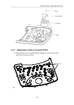
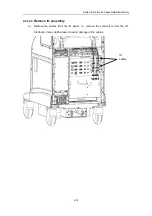
Remove the four screws, pull out encoder cable and take out the encoders.
d)
Remove the self-threading screws and grounding screw, remove the grounding
wire, and take out the keyboard PCBA for replacement.
4.3.9
Replacement of the keyboard
Ejection and retraction of the keyboard assembly are both performed through pushing it
inward.
a)
Push the keyboard assembly inward (as shown by
arrow in the figure below),
①
and then the keyboard will eject outward (as shown by
arrow in the figure).
②
Screw
Encoder
Self-threading screw
Grounding screw
Grounding wire
keyboard
PCBA
Содержание DC-6
Страница 1: ...DC 6 DC 6T DC 6Vet Diagnostic Ultrasound System Service Manual...
Страница 2: ......
Страница 20: ...2 1 2 System Overview 2 1 System Appearance 2 1 1 Complete System with CRT Monitor...
Страница 23: ...System Overview 2 4 2 2 LCD Monitor...
Страница 26: ...System Overview 2 7 2 2 3 Lever of upper support arm...
Страница 66: ...4 1 4 System Structure and Assembly Disassembly 4 1 Exploded View of Complete System...
Страница 97: ...System Structure and Assembly Disassembly 4 32 10 screw caps 13 M4 8 screws Rear cover assembly...
Страница 101: ...System Structure and Assembly Disassembly 4 36 Power boards Card detacher...
Страница 138: ...Checks 6 4 6 3 Safety Checks 6 3 1 Electric safety Refer to Appendix D Electrical Safety Inspection...
Страница 187: ...D 13 ELECTRICAL SAFETY INSPECTION 7 Mains on Applied Part Leakage LIMITS For BF ECG Input and transducer 5000 A...
Страница 191: ...P N 2105 20 40473 V10 0...


