Step 4.
2
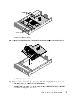
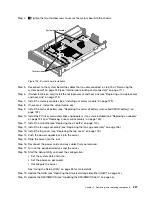
Tighten the two thumbscrews to secure the system board to the chassis.
00
00
00
00
0
0
0
0
000
000
000
000
000
000
0
0
0
00
00
00
00
00
00
00
00
00
00
00
00
00
00000
00000
00000
00000
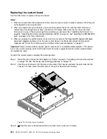
Thumb screws
System board handles
Figure 195. System board installation
Step 5.
Reconnect to the system board the cables that you disconnected in step 13 of “Removing the
system board” on page 223 (see “Internal cable routing and connectors” on page 111).
Step 6.
(Trained technician only) Install the microprocessor and heat sink (see “Replacing a microprocessor
and heat sink” on page 213).
Step 7.
Install the memory modules (see “Installing a memory module” on page 129).
Step 8.
If necessary, install the virtual media key.
Step 9.
Install the coin-cell battery (see “Replacing the coin-cell battery (also called CMOS battery)” on
page 192).
Step 10. Install the PCI riser-card assemblies and adapters, if any were installed (see “Replacing an adapter”
on page 152 and “Replacing a riser-card assembly” on page 145).
Step 11. Install the air baffle (see “Replacing the air baffle” on page 120).
Step 12. Install the fan cage assembly (see “Replacing the fan cage assembly” on page 136).
Step 13. Install the top cover (see “Replacing the top cover” on page 118).
Step 14. Push the power supplies back into the server.
Step 15. Slide the server into the rack.
Step 16. Reconnect the power cords and any cables that you removed.
Step 17. Turn on the peripheral devices and the server.
Step 18. Start the Setup Utility and reset the configuration.
• Set the system date and time.
• Set the power-on password.
• Reconfigure the server.
See “Using the Setup Utility” on page 35 for more details.
Step 19. Update the UUID (see “Updating the Universal Unique Identifier (UUID)” on page 44).
Step 20. Update the DMI/SMBIOS (see “Updating the DMI/SMBIOS data” on page 46).
.
Removing, and replacing components
227
Содержание HX3510-G
Страница 1: ...HX3510 G HX5510 HX5510 C HX7510 Installation and Service Guide Machine Type 8695 ...
Страница 6: ...iv HX3510 G HX5510 HX5510 C HX7510 Installation and Service Guide ...
Страница 62: ...50 HX3510 G HX5510 HX5510 C HX7510 Installation and Service Guide ...
Страница 102: ...90 HX3510 G HX5510 HX5510 C HX7510 Installation and Service Guide ...
Страница 112: ...100 HX3510 G HX5510 HX5510 C HX7510 Installation and Service Guide ...
Страница 1222: ...1210 HX3510 G HX5510 HX5510 C HX7510 Installation and Service Guide ...
Страница 1229: ...People s Republic of China Class A electronic emission statement Taiwan Class A compliance statement Appendix E Notices 1217 ...
Страница 1230: ...Taiwan BSMI RoHS declaration 1218 HX3510 G HX5510 HX5510 C HX7510 Installation and Service Guide ...
Страница 1238: ...1226 HX3510 G HX5510 HX5510 C HX7510 Installation and Service Guide ...
Страница 1239: ......
Страница 1240: ......


