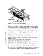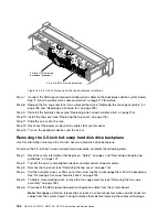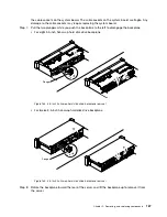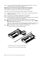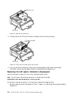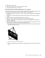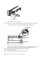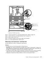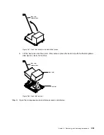
2. Turn off the server and peripheral devices and disconnect the power cords and all external cables, if
necessary.
3. Remove the top cover (see “Removing the top cover” on page 116).
4. Remove the fan cage assembly “Removing the fan cage assembly” on page 135).
5.
1
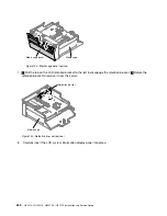
Pull the tab on the LCD retention bracket to the left to disengage the retention bracket.
2
Rotate the
retention bracket to remove it from the server.
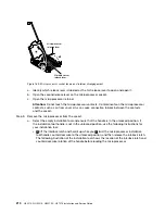
Retention bracket
2
1
Figure 147. Retention bracket removal
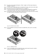
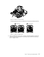
6. Carefully insert the LCD system information display panel into place.
LCD system information
display panel
Figure 148. LCD system information display panel installation
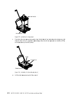
7. Hinge the retention bracket into the slot on the LCD panel assembly and rotate it until it clicks into place.
Retention bracket
Figure 149. Retention bracket installation
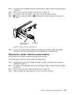
8. Connect the cable to the rear of the LCD system information display panel.
9. Slide the LCD panel assembly into the server until it clicks into place.
.
Removing, and replacing components
197
Содержание HX3510-G
Страница 1: ...HX3510 G HX5510 HX5510 C HX7510 Installation and Service Guide Machine Type 8695 ...
Страница 6: ...iv HX3510 G HX5510 HX5510 C HX7510 Installation and Service Guide ...
Страница 62: ...50 HX3510 G HX5510 HX5510 C HX7510 Installation and Service Guide ...
Страница 102: ...90 HX3510 G HX5510 HX5510 C HX7510 Installation and Service Guide ...
Страница 112: ...100 HX3510 G HX5510 HX5510 C HX7510 Installation and Service Guide ...
Страница 1222: ...1210 HX3510 G HX5510 HX5510 C HX7510 Installation and Service Guide ...
Страница 1229: ...People s Republic of China Class A electronic emission statement Taiwan Class A compliance statement Appendix E Notices 1217 ...
Страница 1230: ...Taiwan BSMI RoHS declaration 1218 HX3510 G HX5510 HX5510 C HX7510 Installation and Service Guide ...
Страница 1238: ...1226 HX3510 G HX5510 HX5510 C HX7510 Installation and Service Guide ...
Страница 1239: ......
Страница 1240: ......


