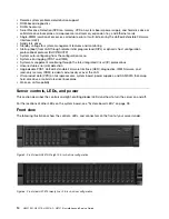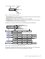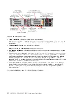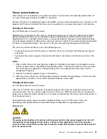
Check log LED
Locator button/
locator LED
Power-control button/
power-on LED
System-error LED
Figure 9. Operator information panel
•
Power-control button and power-on LED:
Press this button to turn the server on and off manually.
The states of the power-on LED are as follows:
Off:
Power is not present or the power supply, or the LED itself has failed.
Flashing rapidly (4 times per second):
The server is turned off and is not ready to be turned on. The
power-control button is disabled. This will last approximately 5 to 10 seconds.
Flashing slowly (once per second):
The server is turned off and is ready to be turned on. You can
press the power-control button to turn on the server.
Lit:
The server is turned on.
•
System-locator button/LED:
Use this blue LED to visually locate the server among other servers.
This LED is also used as a presence detection button. You can use Lenovo XClarity Administrator to
light this LED remotely.
•
Check log LED:
When this yellow LED is lit, it indicates that a system error has occurred. Check the
event log for additional information. See “Event logs” on page 59 for more information about event logs.
•
System-error LED:
When this yellow LED is lit, it indicates that a system error has occurred. A
system-error LED is also on the rear of the server. An LED on the LCD system information display panel (if
available), the operator information panel or on the system board is also lit to help isolate the error. This
LED is controlled by the IMM.
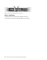
LCD system information display panel
Use this information for an overview of the LCD system information display panel, which displays various
types of information about the server.
Note:
The LCD system information display panel is available only on HX3510-G, HX5510, and HX5510-C.
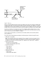
The LCD system information display panel is on the front of the server. The LCD system information display
panel enables you to have quick access to system status, firmware, network, and health information. The
following illustration shows the controls on the LCD system information display panel.
16
HX3510-G, HX5510, HX5510-C, HX7510 Installation and Service Guide
Содержание HX3510-G
Страница 1: ...HX3510 G HX5510 HX5510 C HX7510 Installation and Service Guide Machine Type 8695 ...
Страница 6: ...iv HX3510 G HX5510 HX5510 C HX7510 Installation and Service Guide ...
Страница 62: ...50 HX3510 G HX5510 HX5510 C HX7510 Installation and Service Guide ...
Страница 102: ...90 HX3510 G HX5510 HX5510 C HX7510 Installation and Service Guide ...
Страница 112: ...100 HX3510 G HX5510 HX5510 C HX7510 Installation and Service Guide ...
Страница 1222: ...1210 HX3510 G HX5510 HX5510 C HX7510 Installation and Service Guide ...
Страница 1229: ...People s Republic of China Class A electronic emission statement Taiwan Class A compliance statement Appendix E Notices 1217 ...
Страница 1230: ...Taiwan BSMI RoHS declaration 1218 HX3510 G HX5510 HX5510 C HX7510 Installation and Service Guide ...
Страница 1238: ...1226 HX3510 G HX5510 HX5510 C HX7510 Installation and Service Guide ...
Страница 1239: ......
Страница 1240: ......

