H
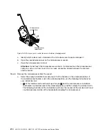
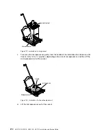
Figure 170. Installation tool handle adjustment
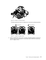
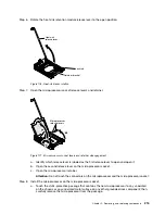
The following illustrations show the installation tool in the locked and unlocked positions.
E
5-
x6
xx
v
3
E
5-
x6
xx
v
4
E
5
-x
6
x
x
v
3
E
5
-x
6
x
x
v
4
E5-x6xx v3
E5-x6xx v4
Lock Position
Unlock Position
Figure 171. Locked and unlocked positions
b.
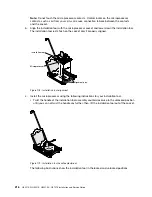
Align the installation tool with the screws, as shown in the following graphic, and lower the
installation tool on the microprocessor. The installation tool rests flush on the socket only
when it is aligned correctly.
.
Removing, and replacing components
211
Содержание HX3510-G
Страница 1: ...HX3510 G HX5510 HX5510 C HX7510 Installation and Service Guide Machine Type 8695 ...
Страница 6: ...iv HX3510 G HX5510 HX5510 C HX7510 Installation and Service Guide ...
Страница 62: ...50 HX3510 G HX5510 HX5510 C HX7510 Installation and Service Guide ...
Страница 102: ...90 HX3510 G HX5510 HX5510 C HX7510 Installation and Service Guide ...
Страница 112: ...100 HX3510 G HX5510 HX5510 C HX7510 Installation and Service Guide ...
Страница 1222: ...1210 HX3510 G HX5510 HX5510 C HX7510 Installation and Service Guide ...
Страница 1229: ...People s Republic of China Class A electronic emission statement Taiwan Class A compliance statement Appendix E Notices 1217 ...
Страница 1230: ...Taiwan BSMI RoHS declaration 1218 HX3510 G HX5510 HX5510 C HX7510 Installation and Service Guide ...
Страница 1238: ...1226 HX3510 G HX5510 HX5510 C HX7510 Installation and Service Guide ...
Страница 1239: ......
Страница 1240: ......


