Ihse Draco tera enterprise 480 Series Скачать руководство пользователя страница 98

Configuration via OSD 

Draco tera enterprise


98 

6.4.4  User Groups 

The matrix allows to bundle the users of a configuration into User Groups. The groups can be used to 
subdivide the users logically or thematically. As an application example you can group all power users 
together. The configuration of User Groups at the same times increases the clarity of the configuration. 
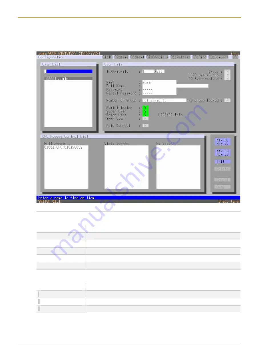
 

Fig. 62 

OSD Menu 

Configuration - User Data


The following functions are available: 

Button 

Function 

New G. 

Create a new group. 

Edit 

Edit an existing user. 

Delete 

Delete an existing user. 

Cancel 

Reject changes. 

Okay 

Apply changes. 


The following keyboard commands are available: 

Keyboard command 

Function 

Add highlighted CPU Device to 

Full access

 list. 

Add highlighted CPU Device to 

Video access

 list. 

Add highlighted CPU Device to 

No access

 list. 


Содержание Draco tera enterprise 480 Series

Страница 1: ...Document 480 xx_REV01 00_en Edition 2022 02 28 USER MANUAL Draco tera enterprise KVM Matrix Switch Series 480 ...

Страница 2: ...ange log for this manual in the chapter 20 page 401 Differences between the various models are clearly described The manufacturer reserves the right to change specifications functions or circuitry of the series described here without notice Information in this manual can be changed expanded or deleted without notice You can find the current version of the manual in the download area of our website...

Страница 3: ...23 3 5 1 2 Draco tera 80 Port Revision 1 23 3 5 1 3 Draco tera 152 Port Revision 1 24 3 5 1 4 Draco tera 160 Port Revision 1 24 3 5 1 5 Draco tera 288 Port Revision 1 25 3 5 1 6 Draco tera 576 Port Revision 1 26 3 5 2 Boards 27 3 5 2 1 Draco tera Controller Board 480 CTRL2 27 3 5 2 2 I O Boards 27 3 5 2 3 Grid Board 27 3 6 Status Indication at the Device 28 3 6 1 Draco tera Controller Board 480 CT...

Страница 4: ...4 3 2 Management Software Toolbar 56 4 3 3 Management Software Mouse Control 56 4 3 4 Management Software Keyboard Control 57 4 3 5 Management Software Reload Options 57 4 3 6 Management Software Context Function 57 4 3 7 Management Software Sort Function 58 4 3 8 Management Software Filter Function 58 4 3 9 Management Software Report Function 59 4 4 Control via Serial Interface 60 5 Installation ...

Страница 5: ...2 Renaming an EXT Unit 101 6 5 2 Configuring EXT Units for USB 2 0 Extender Modules 102 6 5 3 Configuring EXT Units for USB 3 0 USB 2 0 Extender Modules 104 6 5 4 Configuring EXT Units for SDI Usage 106 6 6 Configuring Source Side Settings 108 6 6 1 Setting CPU Devices 108 6 6 2 Setting CPU Groups 110 6 6 3 Configuring CPU Switch 484 Series 112 6 6 4 Assigning Virtual CPU Device 114 6 7 Configurin...

Страница 6: ...ting the Syslog Function 168 7 4 10 Setting the SNMP Function 172 7 4 11 Setting the LDAP Configuration Active Directory 178 7 4 12 Setting the Date and Time 180 7 5 Configuring User Settings 182 7 5 1 Setting the User Access 182 7 5 1 1 Creating a new Standard User Account 184 7 5 1 2 Creating a new LDAP User Account 184 7 5 1 3 Changing a User Account 185 7 5 1 4 Configuring User Access Rights 1...

Страница 7: ...8 7 7 4 Setting CON Device Access Rights for CPU Devices 230 7 7 5 Assigning Virtual CPU Devices 231 7 7 6 Setting CPU Groups 233 7 7 6 1 Creating a new CPU Group 233 7 7 6 2 Assigning a CPU Device to a CPU Group 234 7 7 6 3 Configuring CON Access Rights for CPU Groups 235 7 8 Configuring CON Side Settings 236 7 8 1 Configuring Mouse and Keyboard used in the Extender OSD 236 7 8 2 Setting Extender...

Страница 8: ... Switching Operation via Keyboard 290 8 1 1 Addressing of Master and Sub Matrices 290 8 1 2 Direct Switching via Favorites 290 8 1 3 Instant Switching via Favorites 293 8 1 4 Switching via Macros using Function Keys F1 to F16 293 8 1 5 Switching a CON Unit to a Local Source 293 8 1 6 Switching via Multi Screen Control 294 8 2 Operation via External Switching Solution 294 8 3 Summary of Keyboard Co...

Страница 9: ...Management Software 313 12 1 1 Extended Switching 313 12 1 2 USB 2 0 Switching 315 12 1 3 Predefining Macros 316 12 2 Restarting and Powering down Functions via Management Software 318 12 2 1 Restarting the Matrix 318 12 2 2 Restarting the Controller Board 319 12 2 3 Restarting an I O Board 320 12 2 4 Restarting an Extender Module 321 12 2 5 Powering Down the Matrix 323 13 Maintenance 324 13 1 Mai...

Страница 10: ...yslog Monitoring 351 13 3 2 8 SNMP Monitoring 354 13 3 2 9 Redundancy Function 357 13 3 2 10System Check 358 13 3 2 11Network Check 359 13 3 3 Updating the Matrix Firmware 361 13 3 4 Updating the Extender Module Firmware 364 13 3 4 1 Updating the Extender Module Firmware via Management Software 364 13 3 4 2 Updating the Extender Module Firmware via Mini USB 370 13 3 5 Resetting the Matrix and the ...

Страница 11: ...connect 384 15 3 2 2 Fiber SFP Type LC 384 15 3 2 3 HD BNC SDI 384 15 4 Power Supply Current Draw and Power Consumption 385 15 4 1 Draco tera enterprise Chassis 385 15 4 2 Draco tera enterprise I O and Controller Boards 386 15 5 Environmental Conditions and Emissions 386 15 6 Dimensions 387 15 6 1 Draco tera enterprise Chassis 387 15 6 2 Draco tera enterprise Boards 387 15 7 Weight 388 15 7 1 Drac...

Страница 12: ...ical support for further information about firmware to enter Chinese characters in the OSD Software Version from Release date Tera Tool V5 1 0 0 2022 01 17 1 2 Symbols for Warnings and Helpful Information The meaning of the symbols used for warnings and helpful information in this manual is described below WARNING WARNING indicates a hazardous situation which if not avoided could result in death o...

Страница 13: ...mand Description key Key on the keyboard key key Press keys simultaneously key key Press keys successively 2x key Press key quickly twice in a row like a mouse double click Number number on the keyboard Numeric key at the top end of the alphanumeric keyboard usually used for described operations Number on the numerical pad Numeric key on the numeric pad If the use of the numeric pad is required it...

Страница 14: ...ontaining click mouse click or double click each means a click with the primary left mouse button If the right mouse button has to be used this is explicitly declared in the description 1 4 EU Declaration of Conformity Please find the EU Declaration of Conformity for the product series under www ihse com eu declaration of conformity A copy of the original product specific EU Declaration of Conform...

Страница 15: ...hildren are likely to be present CAUTION Risk of burns due to tremendously heated chassis surface after a long period of operation The surface of the chassis can become very warm after a long period of operation If the chassis surface is touched after a long period of operation this can cause skin burns Protective gloves must be worn to transport a fully equipped chassis after a long period of ope...

Страница 16: ... Ensure that the ground connection is maintained from the outlet socket through to the power supply unit s AC power input Only connect the device to KVM devices using the interconnect cable not to other devices particularly not to telecommunications or network devices Disconnect the Device from the Circuit NOTICE The cable plugs on the device side can contain a lock In the event of a necessary qui...

Страница 17: ...es can be made by Cat X fiber or coaxial cables The matrix serves as a repeater and can be run at a maximum distance of 10 km from the consoles and 10 km from the sources NOTICE Interferences when the immunity limit values are exceeded If the limit values listed in EN 55024 are exceeded reliable and accurate functioning of the devices cannot be guaranteed NOTICE Possible radio interference in a do...

Страница 18: ...e CPU Units CON Units occurs over the respective interconnect cables The Draco tera matrix supports a wide and flexible range of system configurations A part of the Draco tera can be configured e g as a Single Head workstation a part as Dual Head workstation or even as Quad Head workstation In addition there are configurations with KVM and USB 2 0 available Fig 1 Example Single Head installation 1...

Страница 19: ... possibilities to switch CON Devices to CPU Device depending on the access rights of the user or CON Device and the configuration Full Access FA The video is displayed on the monitor of the associated CON Device with USB HID control of the switched CPU Device With enabled Sharing option several users may have Full Access but only one at a time Others will remain in video only Video only VO The vid...

Страница 20: ...rd IEC US Type B C13 2 0 m lockable 480 RED 048 80 Draco tera enterprise 48 80 Port Spare Redundancy PSU 480 RED 160 Draco tera enterprise 152 160 Port Spare Redundancy PSU 480 RED 288 Draco tera enterprise 288 Port Spare Redundancy PSU 480 RED 288 AR Draco tera enterprise 288 Port Spare Redundancy PSU reverse airstream 480 RED 576 Draco tera enterprise 576 Port Spare Redundancy PSU 480 RED 576 AR...

Страница 21: ...era enterprise I O Board 8 Port SFP cages universal free configuration USB 3 0 SDI and HDMI 480 GRD S8 R1 Draco tera enterprise GRID Board Fiber SM 10G 8x1G 1 Port Grid 480 CTRL2 Draco tera enterprise Controller Board version 2 for 48 576 ports versions Controller 480 576 SC Draco tera enterprise 576 satellite controller module Satellite Card Available on demand from Q2 2022 3 3 4 Accessories for ...

Страница 22: ...le RJ10 to D Sub 9 1x IEC country specific power cord C13 2 0 m lockable Quick Setup K480 80 R1 K480 152 R1 Draco tera enterprise 1x Programing cable RJ10 to D Sub 9 2x IEC country specific power cord C13 2 0 m lockable Quick Setup K480 160 R1 K480 288 R1 K480 576 R1 K480 576S R1 K480 576 R2 K480 576S R2 Available on demand from Q2 2022 If anything is missing please contact your distributor ...

Страница 23: ... unit 2 optional 4 Slot for air filter 5 Slot for fan tray 2 6 Slot for controller board 7 Slots for I O boards 1 to 3 8 Slots for I O boards 4 to 6 3 5 1 2 Draco tera 80 Port Revision 1 Fig 5 Interface side Example for Draco tera 80 port revision 1 1 Slot for fan tray 1 2 Slot for power supply unit 1 3 Slot for power supply unit 2 optional 4 Slot for air filter 5 Slot for fan tray 2 6 Slot for co...

Страница 24: ...l 5 Grounding 2x 6 Slot for fan tray 1 7 Slot for controller board 8 Slot for controller board redundancy 9 Slot for fan tray 2 3 5 1 4 Draco tera 160 Port Revision 1 Fig 7 Interface side Example for Draco tera 160 port revision 1 1 Slots for I O boards 1 to 20 2 Slot for power supply unit 1 3 Slot for power supply unit 2 optional 4 Slot for power supply unit 3 optional 5 Grounding 2x 6 Slot for f...

Страница 25: ...Slots for I O boards 1 to 18 2 Slots for I O boards 19 to 36 3 Slot for power supply unit 1 4 Slot for power supply unit 2 optional 5 Slot for power supply unit 3 optional 6 Grounding 2x 7 Slot for fan tray 1 8 Slot for controller board for I O boards 1 to 72 9 Slot for controller board for I O boards 1 to 72 redundancy 10 Slot for fan tray 2 ...

Страница 26: ...ly unit 1 6 Slot for power supply unit 2 7 Slot for power supply unit 3 optional 8 Slot for power supply unit 4 optional 9 Grounding 2x 10 Slot for fan tray 1 11 Slot for controller board for I O boards 54 to 72 12 Slot for controller board for I O boards 54 to 72 redundancy 13 Slot for controller board for I O boards 1 to 36 14 Slot for controller board for I O boards 1 to 36 redundancy 15 Slot f...

Страница 27: ...ort output 7 USB Type A USB HID 1 USB HID device 1 8 USB Type A USB HID 1 USB HID device 2 3 5 2 2 I O Boards Fig 11 Interface side Draco tera I O board 480 C8x 1G and 3G Fig 12 Interface side Draco tera I O board 480 F8x Fig 13 Interface side Draco tera I O board 480 UNI16 1 Locking pin 2 Ports 1 to 8 right to left 3 5 2 3 Grid Board Fig 14 Interface side Draco tera grid board 480 GRD S8 R1 1 Loc...

Страница 28: ... System check while booting or running an update process Flashing red Flashing blue Registration of the controller board has started Flashing blue Flashing red Controller board registration in progress Off Flashing green Operating condition controller board registered at the matrix Flashing blue Flashing green Operating condition with communication between controller board and I O board Flashing r...

Страница 29: ...tus LED network connection 1 3 Link status LED network connection 1 4 Activity status LED network connection 1 Status LEDs for the Network Connection For an easier identification the LED representation and column designation in the table was selected analogously to the LED position on the ports The following tables show the respective LED states colors of the network connection LED Pos 1 3 and act...

Страница 30: ...tatus LED 2 I O board Status LEDs of the I O Board For an easier identification the LED representation and column designation in the table was selected analogously to the LED position on the controller board LED 2 LED 1 Description White White System check while booting or running an update process Flashing red Flashing blue Registration of the I O board has started Flashing blue Flashing red I O ...

Страница 31: ...ection 1G and 3G Cat X Board Fig 21 Interface side Link Connection LEDs Draco tera I O board 1G Cat X 1 Link Status LED 2 Activity Status LED Status LEDs at the I O Ports 1G Cat X For an easier identification the LED representation and column designation in the table was selected analogously to the LED position on the controller board LED 1 LED 2 Description Off Off No link connection available Of...

Страница 32: ...available data traffic is active 3 6 2 3 LEDs for Link Connection 1G and 3G Fiber Board Fig 22 Interface side Link Connection LEDs Draco tera I O board 1G and 3G fiber 1 Link Status LED 2 Activity Status LED Status LEDs at the I O Ports 1G and 3G Fiber For an easier identification the LED representation and column designation in the table was selected analogously to the LED position on the control...

Страница 33: ... UNI Board For an easier identification the LED representation and column designation in the table was selected analogously to the LED position on the controller board LED 1 3 LED 2 4 Description Off Off Port not activated Off Flashing red No link connection available extender module is not detected Green Flashing red Link connection available extender module detection is running Green Off Operati...

Страница 34: ... Grid The following tables show the respective LED states colors of the left LED 1 and right LED 2 of the I O board for the respective situation Pos LED Description 1 3 Off Port not activated 2 4 Off 1 3 Flashing orange No link connection available extender module is not detected 2 4 Off 1 3 Flashing orange Link connection available extender module detection is running 2 4 Flashing green 1 3 Off O...

Страница 35: ... Green Operating condition Red No power supply voltage available The matrix is powered by a second power supply unit Off No power supply voltage available 3 6 3 2 Draco tera 152 160 288 Port Fig 26 Status LEDs for power supply voltage Draco tera 152 160 288 port 1 LED for AC input 2 LED for AC output 3 LED for temperature LEDs for Power Supply Voltage LEDs LED Status Description 1 Green Operating ...

Страница 36: ...or UVP under voltage protected or OVP over voltage protected Orange Fan fault or OTP over temperature protected or stand by on with OCP UVP Off AC input power off 3 6 3 4 Draco tera 576 Port Revision 2 Fig 28 Status LEDs for power supply voltage Draco tera 576 port revision 2 1 LED for power supply voltage LEDs for Power Supply Voltage LEDs LED Status Description 1 Flashing green Stand by on main ...

Страница 37: ...ation 2 Red Attention status error condition 3 Off In use Flashing blue Preparing for extraction Blue Ready to remove 3 6 4 2 Draco tera 152 160 288 576 Port Fig 30 Fan tray status LEDs Draco tera 152 160 288 576 Port 1 Operation LED 2 Alarm LED 3 Hot Swap LED Pos LED Description 1 Off No power to the fan tray Green Normal operation 2 Red Attention status error condition 3 Off In use Flashing blue...

Страница 38: ...described in chapter 3 2 page 18 this chapter shows typical exemplary installations of the Draco tera 3 7 1 Dual Head Installation Fig 31 Example Dual Head installation 1 Dual Head sources 2 Dual Head CPU Units 3 Interconnect cable 4 Draco tera matrix 5 Dual Head CON Units 6 Consoles 2x monitor keyboard mouse ...

Страница 39: ...stem MSC can be set up at multiple sinks Fig 32 Example Single Head installation with MSC 1 Single Head sources 2 Single Head CPU Units 3 Interconnect cable 4 Draco tera matrix 5 Single Head CON Units 6 MSC console e g 4x monitor 1x keyboard 1x mouse If you have a Single Head console e g you can also get access to a Dual Head or Quad Head source However control is only possible at monitor 1 and on...

Страница 40: ...sink can consist of up to sixteen monitors when operating Dual Head Sources In a matrix system MSC can be set up at multiple sinks Fig 33 Example Dual Head installation with MSC 1 Dual Head sources 2 Dual Head CPU Units 3 Interconnect cable 4 Draco tera matrix 5 Dual Head CON Units 6 MSC console e g 8x monitor 1x keyboard 1x mouse Any signal source can be switched to any number of monitors that wi...

Страница 41: ...le Single Head Dual Head and Single Head MSC Installation 1 Single Dual Head sources 2 Single Dual Head CPU Units 3 Interconnect cables 4 Draco tera matrix 5 Single Dual Head CON Units 6 Single Head console 1x monitor keyboard mouse 7 Dual Head console 2x monitor keyboard mouse 8 MSC console e g 4x monitor 1x keyboard 1x mouse ...

Страница 42: ...er matrices are defined as Sub Matrices Sub matrices must be connected to the master matrix via network connector RJ45 on the controller board The Enable LAN Echo option has to be activated at the master matrix see chapter 6 3 1 page 72 If a switching command is performed using the OSD the synchronized matrices will also switch automatically Switching of stacked devices might be delayed by several...

Страница 43: ... The matrix can be used as a video matrix Up to 288 input ports can be switched to up to 288 output ports depending on components and equipment Fig 36 Example Video Matrix 1 Video source e g SDI camera 2 Interconnect cables 3 Matrix 4 Video sink e g monitor ...

Страница 44: ...a matrix grid the grid matrices are interconnected by Grid Lines In this case the sub matrices can be connected directly to the master matrix or between themselves When arranging the grid lines various grid setups can be realized for example a ring setup a hub spoke setup or a fully connected setup of matrices Grid lines can process signals bidirectional Smart Connect Per grid line one KVM connect...

Страница 45: ...le that does not require an installation The management software can be downloaded from the link https www ihse com software Advanced settings can be configured on the Draco tera operating system using the management software Advanced configuration Extended monitoring options System update firmware update Local backup option Documentation API The Draco tera API application programming interface is...

Страница 46: ...g the command mode it will be deactivated automatically The following keyboard commands are used to enter and to exit the command mode and to change the Hot Key Function Keyboard command 2x Left Shift Hot Key factory setting Start the command mode Esc Exit the command mode current Hot Key c new Hot Key Code Enter Change the Hot Key NOTICE In a combined KVM matrix U Switch configuration select diff...

Страница 47: ...he keys on the keyboard Keyboard mapping tables may vary for country specific layouts Note the key position of a freely defined Hot Key when changing the keyboard layout e g from QWERTZ to AZERTY E g if defining 2x a as Hot Key on a German or US keyboard layout the French keyboard layout AZERTY requires then 2x q as Hot Key to be pressed instead Reset the Hot Key To set a Hot Key back to default s...

Страница 48: ...one of the keyboard commands mentioned above possible changes are not saved For information on saving changes see configuration descriptions from chapter 6 9 from page 139 Entering the OSD and the Main Menu To open the main menu proceed as follows 1 Press Hot Key o or the Fast Key to open the OSD The Caps Lock and Scroll Lock LEDs on the keyboard are flashing and the OSD is opened on the display s...

Страница 49: ...revious option in selection fields In the CPU selection list with cursor on a CPU Device Group collapse members of a group Spacebar Switching in selection fields between two conditions e g between ON OFF or Y Yes N No Enter In menus with input fields save data In menus select menu item With buttons confirm selected button Esc In menus with input fields cancel data input without saving In menus wit...

Страница 50: ...tus area topmost two text lines Working area here shown with the main menu Lower status area lowest two text lines Fig 38 OSD Main menu The following functions are available in most of the menus Button Function Cancel Reject changes Okay Confirm changes temporary storage of the active configuration in the volatile memory of the matrix ...

Страница 51: ... the keyboard command twice ID F2 Sort ID names in descending order by pressing the keyboard command once Sort ID names in ascending order by pressing the keyboard command twice Name F3 Go to the next result in the list of results of the search field Next F4 Go to the previous result in the list of results of the search field Previous F5 Refresh the currently shown list Refresh F6 Jump between the...

Страница 52: ...ar 2 Toolbar 3 Tab bar shows connections or configurations 4 Task area 5 Task menu 6 Task menu item 7 Status bar shows config version activated Edit Mode and online mode 8 Working area 9 Tabs for additional menus 10 Buttons The following control elements are included in the menus Designation Element Description Checkbox Function is not active disabled by default or by mouse click Function is activ...

Страница 53: ...2 1 Assigning Copying settings 2 Assigning Removing elements to from an assignment or list 3 Creating Deleting elements 4 Keyboard commands to move elements up down 5 Moving elements up down 6 Tabs for additional functions Element is a placeholder and stands for EXT Units CON CPU Devices Extender Modules Users or Favorites see respective configuration chapters These buttons for main functions are ...

Страница 54: ...f an element to last position Keyboard Command Function Change the index number of elements upwards Change the index number of elements downwards Access Rights Menu In menus to assign access keyboard commands are available shown in the lower area of the tab menu Fig 41 Management software Menu structure Example 3 The following keyboard commands are available in Access assignment tabs Keyboard comm...

Страница 55: ...e of common operating systems Help texts The management software contains its own support function The integrated help texts in the working area of the management software can be activated or deactivated by clicking the checkbox in the upper right corner Auxiliary names tooltips for the menu items can be activated under Extras Options on the Style tab Online help After calling up a function from t...

Страница 56: ...e 8 Download and show a predefined configuration saved on the matrix online 9 Upload a predefined configuration on the matrix online 10 Monitoring online 11 Flash update for single devices 12 Overview of devices in the subnet online mode 13 System check 14 Save status locally online mode 4 3 3 Management Software Mouse Control The following mouse commands are selectable for menu functions Mouse co...

Страница 57: ...s in the menu bar can be executed with the provided keyboard commands e g press Ctrl s to execute Save that are listed to the right of the respective menu item 4 3 5 Management Software Reload Options The information about the current configuration of the matrix shown in the management software can be reloaded in different ways Press F5 on the used keyboard Click Reload in the toolbar Click Edit R...

Страница 58: ...rrow that points downwards Cancel sort Click with the left mouse button once or twice on the head of the sorted column The arrow displayed disappears 4 3 8 Management Software Filter Function Lists and tables in the management software offer a filter function that supports a fast and smooth search The filter entry field is located above the header An active filter is indicated by a green filter sy...

Страница 59: ...nfiguration in a PDF file The report function can be used in both online and offline mode of the management software To create a report proceed as follows 1 Select File Report in the menu bar A selection dialog appears 2 Select contents that should be included in the report Matrix View EXT Units CPU Devices CON Devices and Users 3 Click Next to confirm the selection Fig 44 Management software File...

Страница 60: ...switching single or all connections available both unidirectional and bidirectional In addition there are telegrams for an overall definition of the total switching status and for saving and loading such switching states The matrix optionally provides an echo of all affected switching operations via serial interface or network interface This aids continuous tracking of a matrix configuration and e...

Страница 61: ... the front and middle screws on both sides of the cover 2 For rear rack mount remove the rear and middle screws on both sides of the cover 3 Mount the mounting bracket in the desired position using the screws on the cover chassis 5 2 Setting up the Matrix 5 2 1 Prerequisites for failure free Installation of a Matrix Setup To achieve a failure free installation of a matrix system we recommend to fi...

Страница 62: ...pter 5 4 page 64 The default IP address is 192 168 100 99 and DHCP is deactivated After initial configuration of the matrix and after changing the configuration of the system or the Matrix Grid we recommend to de register the primary controller board and to boot the secondary controller board until the boot process is finished When installing several matrices at the same time it is strongly recomm...

Страница 63: ... via keyboard command Hot Key o It is recommended to rename the automatically created EXT Unit directly see chapter 6 5 1 2 page 101 or see chapter 7 6 2 page 199 5 3 2 Connecting a Source to the Matrix 1 Connect a source to the CPU Unit by using the provided connection cables 2 Connect the CPU Unit to an I O port of the matrix using interconnect cables Cat X or fiber 3 Connect the CPU Unit to the...

Страница 64: ...ns Free memory RAM Recommended 1 GB Operating system Microsoft Windows 8 Windows 8 1 Windows 10 Management software with integrated Java Runtime Tera Tool Downloaded from https www ihse com software Network connection Available between computer and matrix If you want to use the management software without integrated Java Runtime the following requirements must be fulfilled Computer Software Networ...

Страница 65: ...the Firewall If using the management software the Java application file javaw exe has to be released in the firewall settings to use the management software Contact your administrator to configure the firewall settings accordingly Using the management software with integrated Java Runtime a request of the operating system could appear e g if opening the Device Finder 5 4 3 Connecting the Matrix to...

Страница 66: ...nagement software by a double click on the program icon on the desktop or the file in the directory The management software starts in offline mode Fig 46 Management software Landing page in offline mode There are two options to connect to a matrix Via a known IP address Via Device Finder ...

Страница 67: ...ar A login dialog appears 3 Enter the IP address according to the network configuration of the matrix see chapter 7 4 8 page 166 By default the IP address of the matrix is 192 168 100 99 and DHCP is deactivated 4 Enter the username and password of the administrator see chapter 7 5 page 182 By default the username is admin and the password of the administrator is admin 5 Click Login to confirm your...

Страница 68: ...fic matrix is unknown and should be accessed via IP Fig 48 Management software menu Device Finder The following device information is shown in the Device Finder Information Description Broadcast Multicast Search parameters for finding devices Search via broadcast 255 255 255 255 default Input for search within a multicast group multicast address chapter 7 4 8 page 166 Device Name of the device Nam...

Страница 69: ...s By default the search is set via broadcast 255 255 255 255 3 Click Connect in the last column of the Device Finder to establish direct connection to the respective device within the same subnet 4 Enter the username and password of the administrator see chapter 7 5 page 182 By default the username is admin and the password of the administrator is admin 5 Click Login to confirm your entries ...

Страница 70: ...ss is immediately displayed in the OSD To initialize system relevant configuration changes on the matrix the matrix must be restarted The restart of the matrix may take several minutes and the matrix is not available during the restart After changing the configuration of the system we recommend to de register the primary controller board and to boot the secondary controller board until the boot pr...

Страница 71: ...again When leaving the configuration or assignment menu the administrator is logged out automatically 6 2 Overview Configuration Menu Various system functions and options are available in the configuration menu In addition the following functions can be called up here save as active or predefined configuration and shut down restart or reset to factory settings Fig 50 OSD Menu Configuration ...

Страница 72: ...at is used to save the current settings default Standard Info Text Enter additional text to describe the configuration if required default Factory settings Sub Matrix Y If the matrix is defined as a sub matrix in the OSD the user will lose control Control can be recovered by using the keyboard command Hot Key s o The OSD for the matrix that has been defined as sub matrix will be reopened N Functio...

Страница 73: ...n losing the primary link of a CPU Unit default Note This function will have to be activated for a single matrix when using redundant link connections for both matrices in a fully redundant setup N Function not active Synchronize Y Synchronize the sub matrix to the switch status of the master matrix N Function not active default Echo Only Y Synchronize the matrix according to the echo of a second ...

Страница 74: ...sequence Fast Key Keyboard command Open the OSD directly default 00 How often the shortcut key has to be pressed depends on the specified key 1x for function keys or print key 2x for all other keys Settings for Global Hot Key and Fast Key Field Entry Description Hot Key Fast Key 00 No global Hot Key Fast Key defined no modification of the extender module 01 to FE Overwrite the Hot Key Fast Key of ...

Страница 75: ...erprise Configuration via OSD 75 To set the parameters for the system configuration proceed as follows 1 Select Configuration System in the main menu 2 Change the desired settings 3 Click Okay to confirm your entries ...

Страница 76: ...figured Field Entry Description Enable Auto Config Y Enable the automatic creation of a new CPU or CON Device if new extender modules are connected default The new CON or CPU Device is assigned to the automatically created EXT Unit of the extender module N Function not active ID Real CPU Device Numerical Enter the initial value for automatic assignment of real CPU Devices default 1001 ID Virtual C...

Страница 77: ...e Configuration via OSD 77 To set up the automatic creation of CPU Devices or CON Devices proceed as follows 1 Click Configuration System in the main menu 2 Change the desired settings 3 Click Okay to confirm your entries ...

Страница 78: ...o logout is affected Note When the Force User Login function is activated and a user is logged in only the user favorites are available The CON favorites are not accessible N Function not active default Enable User ACL Y CPU Device access is restricted according to the permissions in the ACL Access Control List User login is required Switching by keyboard Hot Keys requires a prior login N Function...

Страница 79: ... which OSD will be closed automatically Select 0 seconds for no timeout default 0 seconds Auto Logout min 0 to 999 minutes Period of inactivity of a logged in user at a CON Device after which he will be automatically logged out In addition to the logout process a complete disconnection from the connected CPU Device occurs under Full Access and Private Mode Select 0 minutes for an automatic user lo...

Страница 80: ...ge 296 When taking over control within 10 s any assigned USB 2 0 extender modules if available will not be switched due to security and stability aspects The shared operation will be deactivated between CON Devices with a different priority as well as the Release Time The switching parameters are set in this menu Fig 54 OSD Menu Configuration Switch The following parameters can be configured Field...

Страница 81: ...quest of K M control by mouse event N Function not active default Release Time sec 0 to 999 seconds Period of inactivity of a connected CON Device after which K M control can be requested by other CON Devices connected to the CPU Device Note Set 0 for an immediate transfer in real time Only one CON Device can have keyboard and mouse control at a time The other CON Devices that are connected to the...

Страница 82: ...matrix is not available during the restart NOTICE Consult your system administrator before changing the network parameters Otherwise unexpected results and failures can occur in combination with the network NOTICE If the syslog function is activated the logging will be started after restarting the matrix or controller card The parameters for the network configuration are set in this menu Fig 55 OS...

Страница 83: ...Unchangeable is retrieved automatically Multicast Byte Enter the Multicast address if there is a Matrix Grid in use within a Multicast group default 255 255 255 255 Network Services Field Entry Description API Service 1 Y Activate the LAN interface at the matrix for access via management software default API service port 5555 5565 N Function not active Grid Service 1 Y Activate Grid interface at t...

Страница 84: ...RR Activate error messages in trace default Y Syslog 1 2 DEB Activate debug messages in Syslog default N Note The debug messages are exclusively for matrix diagnostics They only should be activated after consultation with the manufacturer Otherwise an increased traffic of data might limit the performance of the controller board INF Activate information messages in Syslog default N NOT Activate not...

Страница 85: ...d on a group or organizational unit OU In both cases a user requires to be at least assigned to one group In case of the group all users belonging to a previously defined group on the active directory server are added to the KVM matrix and synchronized In this alternative the organizational structure of the organizational units OUs is added as matrix user group to the KVM matrix configuration This...

Страница 86: ...ated changed or deleted during ongoing operation no restart of the matrix is required To configure and enable the synchronization to the Active Directory server there are three steps required Configuring the LDAP settings Creating an LDAP User see page 94 Creating an LDAP Group see page 99 To configure the LDAP settings proceed as follows 1 Select System Settings Network in the task area 2 Set the...

Страница 87: ... the login data for an SNMPv3 User at the SNMP server can be set in the default settings see section on page 176 NOTICE When using SNMP monitoring for reasons of access security the use of a dedicated network according to the IT Grundschutz Kompendium IT Baseline Protection is recommended The read only community for the MIB file is kvm NOTICE For an activation of the SNMP agent function or the SNM...

Страница 88: ...ender module to the matrix notification about a switched on extender module Notification about a newly established link between extender module and matrix Remove Extender Notification about a removed extender module from the matrix Notification about a switched off extender module Notification about an interrupted link between extender module and matrix Fan Tray 1 Notification about the fan status...

Страница 89: ...as follows 1 Set the Enable Traps option to Y Yes within SNMP Server This function allows an active transmission of trap messages from the SNMP agent to the SNMP server 2 Set the IP address of the SNMP server within Server Address 3 Activate the requested traps by enabling them to Y Yes 4 Click Okay to confirm the changes ...

Страница 90: ...me Protocol SNTP Fig 58 OSD Menu Configuration Date Time The following parameters can be configured Time Server Field Entry Description SNTP Client Y Enable the network time server synchronization N Function not active default SNTP Server Byte Enter the SNTP server IP address default 000 000 000 000 Time Zone Region Set your specific time zone default GMT 00 ...

Страница 91: ...n the main menu 2 Set the SNTP Client option to Y Yes 3 Enter the IP address of your SNTP server into the SNTP Server field 4 Select your time zone in the Time Zone field 5 Click Okay to confirm your settings 6 Restart the matrix The system time will now be provided by the SNTP server Configuring the Real Time Clock without Time Server To set the real time clock without using SNTP proceed as follo...

Страница 92: ... Data The following functions are available Button Function New U Create a new user Edit Edit an existing user Delete Delete an existing user Cancel Reject changes Okay Confirm the changes of an existing user or the creation of a new user account The following keyboard commands are available Keyboard command Function f Add highlighted CPU Device to Full access list v Add highlighted CPU Device to ...

Страница 93: ...og in to the OSD Password Text For standard users optional input of up to 16 characters Can be used to log in to the OSD For LDAP Users case sensitive input of minimum 1 character up to 16 characters Can be used to log in to the OSD Repeat Password Text Repeat user password case sensitive Member of Group Selection Define the assignment to a user group Administrator Y Permission for system configur...

Страница 94: ... bind user from the Active Directory into the field Name 4 Enter the Common Name CN of the bind user from the Active Directory into the field Login Name 5 Enter the password of the bind user from the Active Directory into the fields Password and Repeat Password 6 Click Okay to confirm the creation of the user A matrix configuration should only include one LDAP user and one LDAP group at the same t...

Страница 95: ... keyboard commands see chapter 8 1 1 page 290 Fig 60 OSD Menu Assignments User Favorites To create a favorites list for your own user proceed as follows 1 Select Assignments User Favorites in the main menu 2 Select a CPU Device to be moved to the favorites list on the User Favorites list 3 Press a to move a CPU Device to the favorites list To remove a CPU Device from the favorite list press r 4 Op...

Страница 96: ...r 8 1 4 page 293 To execute user macros the user has to be logged in to the matrix Fig 61 OSD Menu Configuration User List User Macros The following parameters can be configured Field Selection Description Function 01 to 16 Connect P1 CON P2 CPU Set a bidirectional connection from CON Device P1 to CPU Device P2 Connect Video P1 CON P2 CPU Set a Video Only connection from CON Device P1 to CPU Devic...

Страница 97: ...o the CPU Device that is currently connected to CON Device P1 The connection of CON Device P1 remains unchanged Full Access or Video Only Login User console P2 Login a certain user P1 at CON Device P2 P1 CON or CPU Device Name of CON Device or CPU Device P2 CON or CON Device Name of CON Device or CPU Device The macros can also be used to switch to CPU Device groups To create a macro for the select...

Страница 98: ...Groups at the same times increases the clarity of the configuration Fig 62 OSD Menu Configuration User Data The following functions are available Button Function New G Create a new group Edit Edit an existing user Delete Delete an existing user Cancel Reject changes Okay Apply changes The following keyboard commands are available Keyboard command Function f Add highlighted CPU Device to Full acces...

Страница 99: ...roup or the Common Name CN of an organizational unit into the field LDAP OU CN as shown below OU name of the organizational unit CN name of the group Note The field entry must include either OU or CN 6 Click Okay to confirm the creation of the group The Active Directory synchronization can be used now A matrix configuration should only include one LDAP user and one LDAP group at the same time The ...

Страница 100: ...EXT Units Add on modules are not created as independent EXT Units The data of add on modules is included in one EXT Unit together with the associated extender module All EXT Units are managed in this menu This includes the creation of new EXT Units and the deletion of existing EXT Units NOTICE The connection of a fixed port extender module e g USB 2 0 to a Flex Port can cause unintended results EX...

Страница 101: ...o the matrix 1 to 2032 if the primary interconnect port of the extender module is currently connected to a matrix within a matrix grid Port 2 0 if there is no redundant port or if the redundant interconnect port of the extender module is currently not connected to the matrix 1 to 2032 if the redundant interconnect port of the extender module is currently connected to the matrix or to a matrix grid...

Страница 102: ...with digit 9 3 Enter an appropriate name for the EXT Unit in the Name field 4 Enter the port number of the matrix the USB 2 0 extender module is currently connected into the Port field 5 To configure the created EXT Unit as a CON Unit 5 1 Set the USB CON standalone option to Y C 1 in the Input Signals column 5 2 Click Okay to confirm the setting 6 To configure the created EXT Unit as a CPU Unit 6 ...

Страница 103: ...lease Time in the System Settings Switch menu to 10 s or more see chapter 6 3 4 page 80 11 Restart all I O boards on which USB 2 0 EXT Units have been configured or alternatively restart the matrix The USB 2 0 EXT Units are now configured and can be used Manually created EXT Units are always set as fixed port EXT Units This configuration is necessary if you want to switch e g USB 2 0 connections v...

Страница 104: ... configure an SFP for using with USB 2 0 USB 3 0 extender modules proceed as follows 1 Select Configuration EXT Units in the main menu 2 Insert the SFP modules into the matrix and connect the extender module according to the required application One EXT Unit will be created for each SFP module in the EXT Units list The appropriate names always start with UNI In the sub menu EXT Type Universal CON ...

Страница 105: ...Unit 5 The USB 2 0 USB 3 0 CPU CON EXT Unit has to now be either assigned to an existing CPU CON Device or a new CPU CON Device has to be created for the assignment for a CPU Device see chapter 6 6 1 page 108 for a CON Device see chapter 6 7 3 page 119 After assigning EXT Units to CON CPU Devices the USB 2 0 USB 3 0 CON CPU Ext Units are configured and can be used 6 If you use parallel operation w...

Страница 106: ...Insert the SFP modules into the matrix and connect the extender module according to the required application One EXT Unit will be created for each SFP module in the EXT Units list The appropriate names always start with UNI In the sub menu EXT Type Universal CON and Universal CPU are set to Y 3 To configure an EXT Unit as an SDI input 3 1 Select one of the extender modules in the EXT Units list th...

Страница 107: ... confirm the setting Fig 70 OSD Menu Configuration EXT Units Setting an EXT Unit as an SDI output 5 The edited EXT Units for the SDI inputs and outputs has to now be either assigned to an existing CPU CON Device or a new CPU CON Device has to be created for the assignment for a CPU Device see chapter 6 6 1 page 108 for a CON Device see chapter 6 7 3 page 119 After assigning EXT Units to CON CPU De...

Страница 108: ... Fig 71 OSD Menu Configuration CPU Devices The following functions are available Button Function New R Create a new real CPU Device Edit Edit an existing CPU Device Delete Delete an existing CPU Device Cancel Reject changes Okay Apply changes The following parameters can be configured Field Entry Description ID Text Ident number of the CPU Device Name Text Name of the CPU Device Member of Group Se...

Страница 109: ...s both Device and EXT Unit settings to any CPU Unit that is connected to the matrix for the first time Note It is recommended to activate the reference setting for one single CPU Device only N Function not active default 2 Step Access Y Open a pop up window after switching to the particular CPU Device In the background a Video Only connection will be established A confirmation in the pop up window...

Страница 110: ...n menu 2 Select the CPU Device you want to assign an EXT Unit 3 Select the EXT Unit for the assignment in the EXT available list 4 Click Okay The EXT Unit is assigned to the CPU Device now 6 6 2 Setting CPU Groups The KVM matrix allows to bundle the CPU Devices of a configuration into CPU groups The groups can be used to subdivide the CPU Devices logically or thematically As an application example...

Страница 111: ...y set if the CPU Device is assigned to a CPU Group N Function not active default Further parameters are described in chapter 6 6 1 page 108 To create a CPU Group proceed as follows 1 Select Configuration CPU Devices in the main menu 2 Click New G 3 Enter a CPU Group name into the field Name 4 Click Okay The CPU Group is created now To assign a CPU Device to a group proceed as follows 1 Select Conf...

Страница 112: ...ifically configured for a use with a KVM matrix The configuration allows to individually switch the up to eight input signals via OSD Fig 73 OSD Menu Configuration CPU Devices The following functions are available Button Function New S Create a new CPU Switch 484 series New SP Create a CPU EXT Unit for a CPU Switch Edit Edit an existing CPU Device Delete Delete an existing CPU Device Cancel Reject...

Страница 113: ... configure the CPU Switch for an individual switching of the single inputs proceed as follows 1 Select Configuration CPU Devices in the main menu 2 Click New S A new CPU Switch will be created 3 Enter a CPU Switch name into the field Name 4 Assign an EXT Unit to the CPU Switch into the field EXT assigned 5 Click New SP A new CPU Device input for a CPU Switch will be created Port 1 6 Assign the cre...

Страница 114: ...nected to a virtual CPU Device that is assigned to a real CPU Device you only have to change the real CPU Device once and all CON Devices will receive the video signal of the new real CPU Device One real CPU Device can be assigned to several virtual CPU Devices Fig 74 OSD Menu Assignments Virtual CPU Devices The following functions are available Button Function New V Create a new virtual CPU Devic...

Страница 115: ...es in the main menu 2 Select the virtual CPU Device in the Virtual Devices list that has to be assigned to a real CPU Device 3 Click Edit 4 Select the real CPU Device in the Real Devices list that has to be assigned to the selected virtual CPU Device 5 Click Okay to confirm the assignment The selected virtual CPU Device is assigned to the real CPU Device ...

Страница 116: ... Mouse and Keyboard The OSD configuration for mouse and keyboard is made in this menu The settings for mouse and keyboard are CON Device specific and can be set separately for each CON Device Fig 75 OSD Menu Configuration EXT Units The following parameters can be configured Field Entry Description Hor Speed 1 x 1 to 9 Adjustment of the horizontal mouse speed 1 slow 9 fast default 4 Ver Speed 1 x 1...

Страница 117: ... Extender OSD In this menu the parameters for the Extender OSD can be set The settings for mouse and keyboard are CON Device specific and can be set separately for each CON Device When setting the horizontal OSD position a prefixed minus describes the orientation to the right edge of the monitor e g 2 means 2 x 10 20 pixels to this edge When setting a vertical position a prefixed minus describes t...

Страница 118: ...on changes during fade in of Extender OSD default Y N Function not active Display time sec 0 to 999 seconds Duration of OSD fade in default 10 Horizontal Position 127 to 127 pixels Horizontal OSD position default 2 E g value 5 means 5 x 10 px distance to the left border Vertical Position 127 to 127 pixels Vertical OSD position default 3 E g value 5 means 5 x 10 px distance to the top border To cha...

Страница 119: ...luding access rights and assignment to EXT Units Fig 77 OSD Menu Configuration CON Devices The following functions are available Button Function New R Create a real CON Device New V Create a virtual CON Device Edit Edit an existing CON Device Delete Delete an existing CON Device Cancel Reject changes Okay Apply changes ...

Страница 120: ...on not active default LOS Frame Y When the video signal between source and the CPU Unit or the connection between matrix and the CON Unit is lost an orange frame will be displayed When switching to a CPU Device without video signal a blank screen will appear surrounded by an orange frame N Function not active default Disable OSD Y Disable OSD access for the respective CON Device N Function not act...

Страница 121: ... first time Note It is recommended to activate the reference setting for one single CON Device only N Function not active default Fix Color Selection list Show a colored frame when being connected to the respective CPU Device You can select between seven colors The colored frame of the CPU device is displayed with priority to the one of the CON Device To create a CON Device proceed as follows 1 Se...

Страница 122: ...ot Key using the keyboard see chapter 8 1 1 page 290 Fig 78 OSD Menu Assignments CON Favorites To create a favorite list for your own CON Device proceed as follows 1 Select Assignments CON Favorites in the main menu 2 Select a CPU Device to be moved to the favorite list on the CPU Devices list 3 Press a to move a CPU Device to the favorites list To remove a CPU Device from the favorite list press ...

Страница 123: ...a Hot Key and the function keys F1 to F16 see chapter 8 1 4 page 293 The macros can also be used to switch to CPU groups Fig 79 OSD Menu Configuration CON Macros The following parameters can be configured Field Selection Description Function 01 to 16 Connect P1 CON P2 CPU Set a bidirectional connection from CON Device P1 to CPU Device P2 Connect Video P1 CON P2 CPU Set a Video Only connection from...

Страница 124: ...vice that is currently connected to CON Device P1 The connection of CON Device P1 remains unchanged Full Access or Video Only Login User console P2 Login a certain user P1 at CON Device P2 P1 CON or CPU Device Name of CON Device or CPU Device P2 CON or CPU Device Name of CON Device or CPU Device To create a macro for the selected CON Device proceed as follows 1 Select Configuration CON Macros in t...

Страница 125: ...video signal The last assigned CON Device will also have control of the keyboard and mouse A virtual CON Device can be assigned to more than one real CON Devices Fig 80 OSD Menu Assignments Virtual CON Device For an assignment proceed as follows 1 Select Assignments Virtual CON Devices in the main menu 2 Select the real CON Device in the Real Devices list that has to be assigned to a virtual CON D...

Страница 126: ...rd and mouse for operation If the USB HID control has to be performed via several USB HID devices several CON Devices have to be defined as Control CON Device Smooth switching of sources with the mouse is performed by dragging the mouse pointer beyond the respective display to an adjacent display in an arrangement of displays The displays can be arranged side by side in a grid layout or completely...

Страница 127: ... Arrangement field select the layout for the CON Device you want to configure 1 x 4 or 2 x 2 The fields for the configuration of the individual displays will be arranged accordingly 4 Activate the Manual option if the USB HID switching is to be restricted to keyboard commands see chapter 8 1 6 page 294 Manual switching allows the use of multi head consoles 5 Set the Enable option to Y on all CON D...

Страница 128: ...nfigured with Owner Sharing However Control CON Device 1 and 2 cannot access the display of a non Control CON Device at the same time The Control CON Device that first had USB HID control is reset to its own display when the second Control CON Device takes over Changing Multi Screen Control To change the MSC for a setup of a specific I O board proceed as follows 1 Open the OSD of a Control CON Dev...

Страница 129: ... of the cascading you have to configure opposite Tie Lines To connect Tie Lines to the matrices you have to create intended Cascade CON Devices and Cascade CPU Devices that have to be switched within the cascaded environment Define a Master Matrix All further matrices will be configured as Sub Matrices in the configuration process Ensure that the Tie Lines will only be connected after finishing th...

Страница 130: ... the creation of a Cascading CPU Unit 3 Select Configuration CPU Devices in the main menu of the Master Matrix 3 1 Click New R A switchable CPU Device will be created Fig 83 OSD Menu Configuration CPU Devices 3 2 Enter an appropriate Cascading CPU Device into the Name field 3 3 Select the previously configured Cascading CPU Unit in the EXT available list 3 4 Press a to move the Cascading CPU Unit ...

Страница 131: ... EXT Unit will be created Fig 84 OSD Menu Configuration EXT Units 5 2 Enter an appropriate name for the Cascading CON Unit into the Name field 5 3 Enter a port number into the Port field according to the required connection of the Tie Line 5 4 Set the Cascade CON option to Y C 1 in the Input Signals column 5 5 Click Okay to confirm the creation of a Cascading CON Unit ...

Страница 132: ... New R A switchable CON Device will be created Fig 85 OSD Menu Configuration CON Devices 6 2 Enter an appropriate name for the Cascading CON Device into the Name field 6 3 Press a to move the Cascading CON Unit to the EXT assigned list The assignment is displayed in the EXT assigned list 6 4 Click Okay to confirm the assignment ...

Страница 133: ...System 8 Restart all I O boards see chapter 9 2 2 page 309 on which any Master Sub CON Units or CPU Units have been configured or alternatively restart the matrix see chapter 9 2 1 page 308 9 Connect the Tie Lines to the matrices Ensure that each Cascade CON Device on one matrix is connected to Cascade CPU Device on the other matrix to achieve switch ability between two matrices The Matrix Cascadi...

Страница 134: ... 2 Select Configuration EXT Units in the main menu of the Master Matrix 2 1 Click New A new EXT Unit will be created Fig 87 OSD Menu Configuration EXT Units 2 2 Enter an appropriate name for the Cascading CON Unit into the Name field 2 3 Enter a port number into the Port field according to the required connection of the Tie Line 2 4 Set the Cascade CON option to Y C 1 in the Input Signals column 2...

Страница 135: ...reated Fig 88 OSD Menu Configuration CON Devices 3 2 Enter an appropriate name for the Cascading CON Device into the Name field 3 3 Select the previously configured Cascading CON Unit in the EXT available list 3 4 Press a to move the Cascading CON Unit to the EXT assigned list The assignment is displayed in the EXT assigned list 3 5 Click Okay to confirm the assignment ...

Страница 136: ...EXT Unit will be created Fig 89 OSD Menu Configuration EXT Units 5 2 Enter an appropriate name for the Cascading CPU Unit into the Name field 5 3 Enter a port number into the Port field according to the required connection of the Tie Line 5 4 Set the Cascade CPU option to Y C 1 in the Output Signals column 5 5 Click Okay to confirm the creation of a Cascading CPU Unit ...

Страница 137: ...w R A switchable CPU Device will be created Fig 90 OSD Menu Configuration CPU Devices 6 2 Enter an appropriate name for the Cascading CPU Device into the Name field 6 3 Press a to move the Cascading CPU Unit to the EXT assigned list The assignment is displayed in the Extender assigned list 6 4 Click Okay to confirm the assignment ...

Страница 138: ...ystem 8 Restart all I O boards see chapter 9 2 2 page 309 on which any Master Sub CON Units or CPU Units have been configured or alternatively restart the matrix see chapter 9 2 1 page 308 9 Connect the Tie Lines to the matrices Ensure that each Cascade CON Device on one matrix is connected to Cascade CPU Device on the other matrix to achieve switching ability between two matrices The Matrix Casca...

Страница 139: ...ll be possible Administration of Settings Within a Matrix Grid you have to differ between settings that have to be made locally for each matrix and settings that can be made globally so that they are valid for the whole Matrix Grid The settings in the following menus have to be made separately for each matrix or within the master matrix to affect all matrices in the Grid System Access Switch Netwo...

Страница 140: ...of the Grid matrices into the Matrix Grid list starting in the left column Based on the listings a Grid master will be automatically determined for the Matrix Grid The more on the top a matrix is listed in the matrix Grid list the more likely the matrix is considered in the automatic master selection provided that certain criteria like system availability are fulfilled 7 Activate the single matric...

Страница 141: ...Draco tera enterprise Configuration via OSD 141 Fig 93 Menu Configuration System ...

Страница 142: ...e locations as well as the default configuration in the memory of the matrix Save as 6 10 1 Saving the Active Configuration NOTICE Changing or saving configurations blocks the matrix memory and leads to a freeze of all OSD menus for a few seconds The switching connections are not affected by this freeze If you select Auto Save within the system settings an additional automatic saving of the config...

Страница 143: ...ving the active configuration see chapter 6 10 1 page 142 Fig 95 OSD Menu Configuration Save as Saving position Name and detailed information Active Name and detailed information of the current configuration are shown This configuration can be saved function Save see chapter 6 10 1 page 142 Default Name and detailed information of the respective saved configuration are shown This storage location ...

Страница 144: ...sconnect and restart the matrix The selected configuration is loaded on restart and is shown in the menu as active configuration under Active The previously active configuration is overwritten The restart of the matrix may take several minutes and the matrix is not available during the restart Fig 96 OSD Menu Configuration Open To activate a previously saved configuration proceed as follows 1 Sele...

Страница 145: ...ary controller board until the boot process is finished Configurations can be saved as a file that can be stored independent of the matrix We recommend saving a matrix status every time when a configuration has been changed 7 1 Configuring in Online Mode Configurations and system settings can be edited via management software in online mode with an active connection between matrix and management s...

Страница 146: ... Setting saved on the matrix is loaded into the management software 2 Click Download in the toolbar to download the configuration A download wizard will appear and the downloaded configuration will be opened in a new tab 3 Click Disconnect in the toolbar to close the connection from the management software to the matrix 4 Make any edits at the configuration and system settings 5 Click Apply to con...

Страница 147: ...e management software this data can be saved in the default settings Fig 97 Management software menu Example Extras Options Default Settings The following parameters can be configured Option Description IP Hostname Default IP address or host name of the matrix for establishing a connection User Default username for establishing a connection Configuration Directory Default directory for configurati...

Страница 148: ... Size Tooltip and Theme The font size the theme and the display of tooltips for the toolbar can be set in this menu 1 Select Extras Options in the menu bar and open the Style tab 2 Select the desired font size Normal or Large 3 Tick the Show Toolbar Button Text checkbox to display a tooltip when hovering over a in the toolbar 4 Select the color theme for the management software Default Dark Gray L...

Страница 149: ...ge tab 2 Select the desired language within the management software and the corresponding charset 3 Click Ok to confirm the changes 4 Close the management software and restart it Fig 99 Management software menu Extras Options Language If using only Linux based matrix systems it is possible to enter Chinese characters Therefore a respective firmware package has to be installed and the Chinese Encod...

Страница 150: ...ower backplane and fan firmware Show the firmware of the fans and the power backplane in the menu Status Updates Status Matrix Firmware Enable single I O board update on compact switch Option available only for Draco tera compact and Draco tera flex Enable splitted firmware update matrix and extender for master and sub part of the 576 matrix Option available only for Draco tera enterprise 576 To s...

Страница 151: ...fault SWITCH_01 The device name is used as the host name in the network Name Text Enter the name of the configuration that is used to save the current settings default Standard Info Text Enter additional text to describe the configuration if required default Factory settings Sub Matrix Activated If the matrix is defined as a sub matrix in the OSD the user will lose control Control can be recovered...

Страница 152: ...ntroller via LAN connection or when using stacking with two or more matrices Deactivated Function not active default Enable Redundancy Activated Automatically switch to the second link of a connected redundant CON Unit when losing the primary link of a CPU Unit default Note This function will have to be activated for both matrices in a fully redundant setup Deactivated Function not active Primary ...

Страница 153: ...e second controller board is not available Connections will be disconnected Deactivated Function not active default To set parameters for the system configuration proceed as follows 1 Click System Settings System in the task area 2 Click Activate Edit Mode in the toolbar 3 Change the desired settings 4 Click Apply to confirm your entries 5 Click Deactivate Edit Mode in the toolbar ...

Страница 154: ... can be configured Field Entry Description Enable Auto Config Activated Enable the automatic creation of a new CPU or CON Device if new extender modules are connected default The new CON or CPU Device is assigned to the automatically created EXT Unit of the extender module Deactivated Function not active ID Real CPU Device Numerical Enter the initial value for automatic assignment of real CPU Devi...

Страница 155: ...of CPU Devices or CON Devices proceed as follows 1 Click System Settings System in the task area 2 Click the Automatic ID tab in the working area 3 Click Activate Edit Mode in the toolbar 4 Change the desired settings 5 Click Apply to confirm your entries 6 Click Deactivate Edit Mode in the toolbar ...

Страница 156: ... Keyboard command Open the OSD via direct access default 00 How often the shortcut key has to be pressed depends on the specified key 1x for function keys or print key 2x for all other keys Settings for Global Hot Key and Fast Key Field Entry Description Hot Key Fast Key 00 No global Hot Key Fast Key defined no modification of the extender module 01 to FE Overwrite the Hot Key Fast Key of the exte...

Страница 157: ... Right Shift F6 Right Alt Hot Key or Fast Key set in the CON EXT Units have priority over the global settings To configure global OSD settings proceed as follows 1 Click System Settings System in the task area 2 Click Activate Edit Mode in the toolbar 3 Click the Global OSD Settings tab in the working area 4 Change the desired settings 5 Click Apply to confirm the changes 6 Click Deactivate Edit M...

Страница 158: ... x 1 to 9 Adjust the vertical mouse speed with 1 fast 9 slow default 5 Double click Time ms 100 to 800 Adjust the time slot for a double click default 200 Keyboard Layout Region Set the OSD keyboard layout according to the keyboard used default German DE To set up the mouse and keyboard for usage at the controller board proceed as follows 1 Click System Settings System in the task area 2 Click the...

Страница 159: ...via LAN connection Note This function should be enabled when using a media controller via LAN connection or when using stacking with two or more matrices Deactivated Function not active default Synchronize Activated Synchronize the sub matrix to the switch status of the master matrix Deactivated Function not active default Echo Only Activated Synchronize the matrix according to the echo of a secon...

Страница 160: ...et the network address of the master matrix default 000 000 000 000 To set up the synchronization of the sub and the master matrix proceed as follows 1 Click System Settings System in the task area 2 Click the Synchronization Mode tab in the working area 3 Click Activate Edit Mode in the toolbar 4 Change the desired settings 5 Click Apply to confirm your entries 6 Click Deactivate Edit Mode in the...

Страница 161: ...Note When using the Force User Login function CON Device ACL Access Control List is still active When the Force User Login function is activated and a user is logged in only the user favorites are available The CON favorites are not accessible Deactivated Function not active default Enable User ACL Activated CPU Device access is restricted according to the permissions in the ACL User login is requ...

Страница 162: ...D will be closed automatically Select 0 seconds for no timeout Default 0 seconds Auto Logout min 0 to 999 minutes Period of inactivity of a logged in user at a CON Device after which he will be automatically logged out In addition to the logout process a complete disconnection from the connected CPU Device occurs under Full Access and Private Mode Select 0 minutes for an automatic user logout when...

Страница 163: ...board may also be used to take over control To allow a smooth and accurate function of the shared operation you should use identical mice and keyboards They should be connected to the same USB HID ports of each CON Unit The alternative is using the USB HID Ghosting see chapter 8 3 2 2 page 296 When taking over control within 10 s any assigned USB 2 0 EXT Unit if available will not be switched due ...

Страница 164: ...l be disconnected Note To share K M control Force Disconnect has to be deactivated and Enable Video Sharing has to be activated Deactivated Function not active default CPU Auto Connect Activated If a CON Device is not connected to a CPU Device you can establish an automatic connection to the next available CPU Device by hitting any key or mouse button Deactivated Function not active default CPU Ti...

Страница 165: ... 6 Tick the Mouse Connect checkbox if taking over control by a keyboard movement should be possible 7 Define a Release Time of inactivity 0 to 999 seconds after which control can be taken over 8 Click Apply to confirm the changes 9 Click Deactivate Edit Mode in the toolbar Keyboard Connect and or Mouse Connect are only effective if Force Connect and or CPU Auto Connect are activated If the Keyboar...

Страница 166: ...administrator before changing the network parameters Otherwise unexpected results and failures can occur in combination with the network The parameters for the network configuration are set in this menu Fig 108 Management software menu System Settings Network General The following parameters can be configured Field Status Description Dual Interface Activated Redundant network connection is deactiv...

Страница 167: ...yte Input of the Multicast address if there is a Matrix Grid in use within a Multicast group default is broadcast 255 255 255 255 Network Services Field Status Description API Service Activated Activate the LAN interface at the matrix activated for access via management software API service port 5555 5565 default Deactivated Function not active SSL Support Activated Activate SSL encryption for API...

Страница 168: ...Status Description Enable Syslog Activated Activate the Syslog server to query status requests Deactivated Function not active default Syslog Server Byte Enter the IP address of the Syslog servers in the form 192 168 1 1 Port Byte Enter the Syslog port default 514 Log Level Debug Activate debug messages in Syslog default deactivated Note The debug messages are exclusively for matrix diagnostics On...

Страница 169: ...ting the Syslog Options To set or activate the presetting proceed as follows 1 Click Extras Options in the menu bar and open the Syslog tab 2 Enter the appropriate data 3 Click Ok to confirm the entries 4 Close the management software and restart it Fig 110 Management software menu Extras Options Syslog The following options are available Option Description Log File Directory Default directory to ...

Страница 170: ...fication Enables acoustic notification for errors Autostart When starting the management software the Syslog logging will be started in the background Open Monitoring Tab When starting the management software the monitoring tab will be opened Activating I O Board Diagnosis For dedicated trouble shooting Syslog can be enabled for selected I O board in this menu Fig 111 Management software menu Stat...

Страница 171: ...messages proceed as follows 1 Click Status Updates Miscellaneous in the task area The I O Board Diagnostic tab opens in the working area 2 Click Activate Edit Mode in the toolbar 3 Select the desired I O boards to activate the additional diagnosis Messages of the selected I O boards will be added to the Syslog protocol 4 Click Send to send the settings to the matrix 5 Click Deactivate Edit Mode in...

Страница 172: ...he login data for an SNMPv3 User at the SNMP server can be set in the default settings see section on page 176 NOTICE When using SNMP monitoring for reasons of access security the use of a dedicated network according to the IT Grundschutz Kompendium IT Baseline Protection is recommended The read only community for the MIB file is kvm NOTICE For an activation of the SNMP agent function or the SNMP ...

Страница 173: ...on about removal of an I O board out of a slot Invalid I O Board Notification about a wrong firmware installed on the I O board Insert Extender Notification about a newly connected extender module to the matrix notification about a switched on extender module Notification about a newly established link between extender module and matrix Remove Extender Notification about a removed extender module ...

Страница 174: ...of the SNMP agent is granted 5 Click Apply to confirm the changes 6 Click Deactivate Edit Mode in the toolbar Activating SNMP Traps To activate active reporting of the SNMP traps proceed as follows 1 Click System Settings Network in the task area 2 Click Activate Edit Mode in the toolbar 3 Click the SNMP tab in the working area 4 Tick the Enable Traps checkbox within the SNMP Trap area 5 Enter the...

Страница 175: ...le Directory Default directory to store the log files Log File Name Default name of the log file Log File Extension Default extension for the log file Daily Log Files Log files are stored every 24 hours daily Maximum Log File Size KB Allowed maximum size of log file When reaching the maximum log file size a new log file will be created Maximum Number of Log Files Allowed maximum number of log file...

Страница 176: ...e transmitted Ensure the login data username and password in both settings are identical see chapter 7 5 1 page 182 To configure the login data for an SNMPv3 User at the SNMP server proceed as follows 1 Click Extras Options in the menu bar and open the SNMP tab 2 Click Manage SNMPv3 Users A list appears with already created SNMPv3 users 3 Click Add User A dialog window appears 4 Enter the required...

Страница 177: ...ion Username SNMPv3 username Authentication Protocol Only SHA protocol no selection available Authentication Password Authentication password for the SNMPv3 user case sensitive input of minimum 8 characters up to 16 characters Privacy Protocol Only DES protocol no selection available Privacy Password Must be identical to the password of the authentication password ...

Страница 178: ...equires to be at least assigned to one group In case of the group all users belonging to a previously defined group on the active directory server are added to the KVM matrix and synchronized In this alternative the organizational structure of the organizational units OUs is added as matrix user group to the KVM matrix configuration This means that the organizational unit OU that includes the user...

Страница 179: ...er and the LDAP group can be created changed or deleted during ongoing operation no restart of the matrix is required To configure and enable the synchronization to the Active Directory server there are three steps required Configuring the LDAP settings Creating an LDAP User see page 184 Creating an LDAP Group see page 195 To configure the LDAP settings proceed as follows 1 Click System Settings N...

Страница 180: ...lowing parameters can be configured SNTP Field Entry Status Description SNTP Activated Enable the network time server synchronization Deactivated Function not active default SNTP Server Byte Enter the SNTP server IP address default 000 000 000 000 Time Zone Region Set your specific time zone default GMT 00 Real Time Clock Field Description Date Date and time of the real time clock Get Local Time G...

Страница 181: ...7 Restart the matrix After the restart the system time is now provided by the SNTP server 8 Click Deactivate Edit Mode in the toolbar Configuring the Real Time Clock without Time Server To set the real time clock without using SNTP proceed as follows 1 Click System Settings Date and Time in the task area 2 Click Activate Edit Mode in the toolbar 3 Set the current date in the Date and Time section ...

Страница 182: ...ttings and permissions are set in this menu Fig 117 Management software menu User Settings Users Groups Users NOTICE Failed SNMP logging If the login data of the SNMPv3 user differs between the matrix and the SNMP server no SNMP loggings are transmitted Ensure the login data username and password in both settings are identical see section on page 176 ...

Страница 183: ...is the userPrincipalName automatically retrieved Can be used to log in to the OSD Password Text For standard users optional input of up to 16 characters Can be used to log in to the OSD For LDAP Users case sensitive input of minimum 1 character up to 16 characters Can be used to log in to the OSD Priority Value Priority of the user Administrator Activated Permission for system configuration and al...

Страница 184: ...d 8 Enter general access permissions 9 Set user permissions for CPU Device access paste function 10 Set user favorites for OSD access 11 Click Apply to confirm the new user settings 12 Click Deactivate Edit Mode in the toolbar 7 5 1 2 Creating a new LDAP User Account 1 Click User Settings Users Groups in the task area 2 Click Activate Edit Mode in the toolbar 3 Click New User A selection dialog ap...

Страница 185: ... Rights To configure user access rights for CPU Devices proceed as follows 1 Click User Settings Users Groups in the task area 2 Click Activate Edit Mode in the toolbar 3 Select a user in the Users list 4 By clicking with the right mouse button once on a CPU Device in one of the respective access lists Full Access Video Access and No Access a context menu for selection appears in which the respect...

Страница 186: ...ive user for the favorites list in the Users list 4 Click the Favorites tab in the working area 5 Select the CPU Devices in the CPU Device available list that should be added to the favorites list Favorite CPU Devices By pressing and holding down Ctrl at the same time more than one CPU Device can be highlighted 6 Click to move the highlighted CPU Devices to the favorites list By clicking all CPU D...

Страница 187: ... 1 4 page 293 To execute user macros the user has to be logged in to the matrix Fig 119 Management software menu User Settings Users Groups Users Macros The following parameters can be configured Field Selection Description Function 01 to 16 Connect P1 CON P2 CPU Set a bidirectional connection from CON Device P1 to CPU Device P2 Connect Video P1 CON P2 CPU Set a Video Only connection from CON Devi...

Страница 188: ...ser proceed as follows 1 Click User Settings Users Groups in the task area 2 Click Activate Edit Mode in the toolbar 3 Select the user for which macros are to be created 4 Open the Macros tab 5 Select in the Key field the function key for which a macro has to be created 6 Double click in the Function column to display a list of all available commands that should be part of the macro 7 Select the d...

Страница 189: ...the login for the OSD should be restricted 4 Click the Login Lock tab in the working area 5 Select the CON Devices in the Allowed Login list that should be added to the list of locked CON Devices Locked Login By pressing and holding down Ctrl at the same time more than one CON Device can be highlighted 6 Click to move the highlighted CON Devices to Locked Login list By clicking all CON Devices fro...

Страница 190: ...ed settings 7 Click Next Fig 121 Management software menu Users Groups Users Assign Settings to Select Settings A query to start the assignment appears 8 Select the user in the Available to assign settings to list to which the settings are to be assigned By pressing and holding down Ctrl at the same time more than one user can be highlighted 9 Click to move the highlighted user to the Assign setti...

Страница 191: ...Draco tera enterprise Configuration via Management Software 191 Fig 122 Management software menu Users Groups Users Assign Settings to Assign Settings ...

Страница 192: ...pressing and holding down Ctrl at the same time more than one user can be highlighted 4 Click Copy Settings from below the user list A query to select the settings appears 5 Tick the checkboxes to select the desired settings to be copied 6 Click Next Fig 123 Management software menu Users Groups Users Select Settings A query to start the assignment appears 7 Select the user in the selection list f...

Страница 193: ...Draco tera enterprise Configuration via Management Software 193 Fig 124 Management software menu Users Groups Users Copy Settings ...

Страница 194: ...of User Groups at the same time increases the clarity of the configuration Fig 125 Management software menu User Settings Users Groups Groups User Assignment Creating a Standard User Group To create and configure a User Group proceed as follows 1 Click User Settings Users Groups in the task area 2 Click Activate Edit Mode in the toolbar 3 Click the Groups tab in the working area 4 Click New Group ...

Страница 195: ...e one LDAP user and one LDAP group at the same time The LDAP user and the LDAP group can be created changed or deleted during ongoing operation No restart of the matrix is required Assigning a User to a Group To assign a user to a group proceed as follows 1 Click User Settings Users Groups in the task area 2 Click Activate Edit Mode in the toolbar 3 Click the Groups tab in the working area 4 Selec...

Страница 196: ... of add on modules is included in one EXT Unit together with the associated extender module All EXT Units are managed in this menu This includes the creation of new EXT Units and the deletion of existing EXT Units NOTICE The connection of a fixed port EXT Unit e g USB 2 0 to a Flex Port can cause unintended results EXT Units for USB 2 0 extender modules have to be created manually see chapter 7 6 ...

Страница 197: ...B 2 0 CON Unit USB 2 0 CPU Unit Deactivated Function not active default HDCP Active Activated HDCP is active on the respective extender module retrieved automatically Deactivated Function not active default CPU CON Assigned Assigned CPU Device or CON Device Redundant Port 0 or 1 to 2032 Up to 576 ports if using a single matrix or up to 2032 ports within a matrix grid 0 if there is no redundant por...

Страница 198: ...task area 2 Select the EXT Unit of the extender module whose type is to be displayed The extender module type is displayed on the right side of the working area The Basic column stands for the extender module of the selected EXT Unit The Part A and Part B columns stand for the add on module of the selected EXT Unit Fig 127 Management software menu Extender Devices EXT Units Expert View Extender Ty...

Страница 199: ...right side of the working area Fig 128 Management software menu Extender Devices EXT Units Firmware Version Add on modules are shown together with the associated extender module in one EXT Unit 7 6 2 Renaming an EXT Unit To rename an EXT Unit after initially connecting an extender module to the matrix proceed as follows 1 Click Extender Devices EXT Units in the task area 2 Click Activate Edit Mode...

Страница 200: ...ters mean Fig 129 Management software menu Extender Devices EXT Units Read parameters The following functions are available in the Parameters tab Button Function Open Open locally saved parameters Save As Save the parameters locally file Config txt Read Read the parameters of the extender module Transmit Transmit the parameters to the extender module and activate Reset Reset the parameters of the ...

Страница 201: ...the reading The parameters of the extender module are read out and displayed on the right side of the working area At the same time the connection will be disconnected for a few seconds Fig 130 Management software menu Extender Devices EXT Units Displayed parameters 7 6 3 2 Changing Parameters To change parameters of an extender module proceed as follows 1 Click Extender Devices EXT Units in the t...

Страница 202: ...ea 2 Click Activate Edit Mode in the toolbar 3 Select the EXT Units of the extender module whose parameters are to be displayed 4 Click the Parameter tab on the right side of the working area 5 Click Read in the symbol bar of the tab A query to read the parameters appears 6 Click Yes to confirm the reading The parameters of the extender module are read out and displayed on the right side of the wo...

Страница 203: ... EXT Units Select EXT Units A query to start the assignment appears 12 Tick the Confirm to continue checkbox to confirm the start of the assignment 13 Click Next to start of the assignment Fig 133 Management software menu Extender Devices EXT Units Start parameter assignment The progress of the parameter assignment is displayed ...

Страница 204: ...tera enterprise 204 14 Click Finish when the parameter assignment is completed green Fig 134 Management software menu Extender Devices EXT Units Assignment finished The parameter assignment is finished 15 Click Deactivate Edit Mode in the toolbar ...

Страница 205: ...r Devices EXT Units in the task area 2 Click Activate Edit Mode in the toolbar 3 Select the CON EXT Unit whose settings are to be assign to another CON EXT Unit 4 Click Assign Settings to below the EXT Units list A query to select the settings appears 5 Tick the checkboxes to select the desired settings 6 Click Next Fig 135 Management software menu Extender Devices EXT Units Assign Settings Select...

Страница 206: ...ettings to list 10 Click Finish The settings are immediately assigned to the selected CON EXT Units 11 Click Deactivate Edit Mode in the toolbar Fig 136 Management software menu Extender Devices EXT Units Assign Settings Assign Settings to Copying Settings from an EXT Unit To copy settings from a CON EXT Unit to another one proceed as follows 1 Click Extender Devices EXT Units in the task area 2 C...

Страница 207: ...es EXT Units Select Settings A query to start the assignment appears 7 Select the CON EXT Unit in the selection list from which the settings are to be copied 8 Click Finish The settings are immediately copied to the selected CON EXT Units Fig 138 Management software menu Extender Devices EXT Units Copy Settings ...

Страница 208: ...ollows 1 Select Extender Devices EXT Units in the task area 2 Click Activate Edit Mode in the toolbar 3 Click New Unit A selection dialog appears 4 Select Choose template in the selection box if you want to use a template for a USB 2 0 CON Unit or a USB 2 0 CPU Unit An EXT Unit with an eight digit ID will be created starting with digit 9 5 Enter an appropriate name for the EXT Unit in the Name fie...

Страница 209: ... 223 for a CON Device see chapter 7 8 3 page 240 10 If you use parallel operation within the matrix set the Release Time in the System Settings Switch menu to 10 s or more see chapter 7 4 7 page 163 11 Restart all I O boards on which USB 2 0 EXT Units have been configured or alternatively restart the matrix The USB 2 0 EXT Units are now configured and can be used Manually created EXT Units are alw...

Страница 210: ...tender Devices EXT Units Expert View Extender Type To configure an SFP for using with USB 2 0 USB 3 0 extender modules proceed as follows 1 Select Configuration EXT Units in the main menu 2 Insert the SFP modules into the matrix and connect the extender module according to the required application One EXT UNIT will be created for each SFP module in the EXT Units list The appropriate names always s...

Страница 211: ...he USB 2 0 USB 3 0 CPU CON EXT Unit has to now be either assigned to an existing CPU CON Device or a new CPU CON Device has to be created for the assignment for a CPU Device see chapter 7 7 3 page 223 for a CON Device see chapter 7 8 3 page 240 After assigning EXT Units to CON CPU Devices the USB 2 0 USB 3 0 CON CPU Ext Units are configured and can be used 6 If you use parallel operation within th...

Страница 212: ...roceed as follows 1 Select Configuration EXT Units in the main menu 2 Insert the SFP modules into the matrix and connect the extender module according to the required application One EXT UNIT will be created for each SFP module in the EXT Units list The appropriate names always start with UNI 3 To configure an EXT Unit as an SDI input 3 1 Select one of the extender modules in the EXT Units list th...

Страница 213: ...etting 4 4 Click Yes to restart the I O board upon request in the dialog 5 The edited EXT Units for the SDI inputs and outputs has to now be either assigned to an existing CPU CON Device or a new CPU CON Device has to be created for the assignment for a CPU Device see chapter 7 7 3 page 223 for a CON Device see chapter 7 8 3 page 240 After assigning EXT Units to CON CPU Devices the SDI inputs and ...

Страница 214: ...e same time General Preparation To use the USB HID Ghosting management via management software it is required that USB HID Ghosting has been already activated at a CPU Unit via keyboard command or the USB HID Ghosting information is already available as a file with the file extension dhg Several general options are available For these options select the menu Extender Devices EXT Units in the task ...

Страница 215: ... read the USB HID Ghosting appears 6 Click Yes to confirm the reading The current USB HID Ghosting information of the CPU extender module is read out and displayed on the right side of the working area At the same time the connection will be disconnected for a few seconds 7 7 1 2 Loading a USB HID Ghosting Template To load a USB HID Ghosting template file extension dhg for a further distribution p...

Страница 216: ...D Ghosting appears 6 Click Yes to confirm the reading The current USB HID Ghosting information of the CPU extender module is read out and displayed on the right side of the working area At the same time the connection will be disconnected for a few seconds 7 Click Assign in the symbol bar of the tab A query to assign the USB HID Ghosting appears 8 Select those EXT Units in the Available to assign ...

Страница 217: ...iguration via Management Software 217 Fig 145 Management software menu Extender Devices EXT Units Assign to A query to start the assignment appears 12 Tick the Confirm to continue checkbox to confirm the start of the assignment ...

Страница 218: ...USB HID Ghosting assignment is completed green Fig 147 Management software menu Extender Devices EXT Units Assignment finished The USB HID Ghosting assignment is finished 15 Click Deactivate Edit Mode in the toolbar Further options To locally store existing USB HID Ghosting information of a selected CPU EXT Unit click Save As in the symbol bar of the tab To delete existing USB HID Ghosting informa...

Страница 219: ...required that the EDID has been already transmitted at a CPU Unit via keyboard command or the EDID is already available as a file with the extension bin Several general options are available For these options select the menu Extender Devices EXT Units in the task area select the EXT Unit of an extender module and select the EDID tab EDID 2 for Dual Head in the working area Fig 148 Management softw...

Страница 220: ...ck Extender Devices EXT Units in the task area 2 Click Activate Edit Mode in the toolbar 3 Click the EDID tab on the right side of the working area 4 Select the EXT Unit of a CPU extender module to transmit the EDID to 5 Click Open in the symbol bar of the tab 6 Go to the respective template with the file extension bin and click Select 7 Click Transmit in the symbol bar of the tab A query for tran...

Страница 221: ...gn the EDID appears 7 Select the EXT Units of those extender modules in the Available to assign settings to field that are intended to receive the EDID By pressing and holding down Ctrl at the same time more than one EXT Unit can be highlighted 8 Click to move the highlighted EXT Units to the Assign settings to list By clicking all EXT Units will be moved to the Assign settings to list 9 To remove...

Страница 222: ...u Extender Devices EXT Units Confirm assignment The progress of the USB HID Ghosting assignment is displayed 13 Click Finish when the USB HID Ghosting assignment is completed green Fig 152 Management software menu Extender Devices EXT Units Assignment finished The EDID assignment is finished 14 Click Deactivate Edit Mode in the toolbar ...

Страница 223: ... 153 Management software Menu Extender Devices CPU Devices Extender Assignment The following parameters can be configured Field Entry Status Description ID Text Ident number of the CPU Device Name Text Name of the CPU Device Virtual Device Activated The CPU Device was created as a virtual CPU Device Deactivated Function not active default Allow Private Activated Allow switching to the respective C...

Страница 224: ...e Access Activated Activate an access limitation for the case that a CPU Device is already connected via Full Access connection When having the same priorities any additional access to the CPU Device can only be established with a Video Only connection Having a lower priority any additional connection is not possible Only when having a higher priority an additional Full Access connection can be es...

Страница 225: ...the CPU Devices list 4 Click the CPU Access Control tab on the right side of the working area 5 Select an EXT Unit in the Extender available list that you want to assign to the CPU Device By pressing and holding down Ctrl at the same time more than one EXT Unit can be highlighted 6 Click to move the highlighted EXT Units to the Extender assigned list By clicking all available EXT Units from the Ex...

Страница 226: ...vices in the task area 2 Click Activate Edit Mode in the toolbar 3 Select the CPU Device whose settings are to be assign to another CPU Devices 4 Click Assign Settings to below the CPU Device list A query to select the settings appears 5 Tick the checkboxes to select the desired settings 6 Click Next Fig 154 Management software menu Extender Devices CPU Devices Select Settings A query to start the...

Страница 227: ... the highlighted CPU Device to the Assign settings to list By clicking all CPU Devices will be moved to the Assign settings to list 9 To remove highlighted CPU Devices from the Assign settings to list click By clicking CPU Devices will be removed from the Assign settings to list 10 Click Finish The settings are immediately assigned to the selected CPU Devices 11 Click Deactivate Edit Mode in the t...

Страница 228: ...ctivate Edit Mode in the toolbar 3 Select the CPU Device to copy the settings to By pressing and holding down Ctrl at the same time more than one CPU Device can be highlighted 4 Click Copy Settings from below the CPU Device list A query to select the settings appears 5 Tick the checkboxes to select the desired settings 6 Click Next Fig 156 Management software menu Extender Devices CON Devices Sele...

Страница 229: ...oftware 229 7 Select the CPU Device in the selection list from which the settings are to be copied 8 Click Finish The settings are immediately copied to the selected CPU Devices Fig 157 Management software menu Extender Devices CPU Devices Copy Settings ...

Страница 230: ... Activate Edit Mode in the toolbar 3 Select CPU Device in the CPU Devices list which should get access rights by a CON Device 4 Click the CON Access Control tab 5 By clicking with the right mouse button once on a CON Device in one of the respective access lists Full Access Video Access and No Access a context menu for selection appears for changing the respective CON Device access rights Alternati...

Страница 231: ...ll CON Devices will receive the video signal of the new real CPU Device One real CPU Device can be assigned to several virtual CPU Device NOTICE If the Auto Send checkbox is ticked in the lower left corner of the workspace the switching operations will be performed immediately without user confirmation by clicking Send Fig 159 Management software menu Assignment Virtual CON Devices The following f...

Страница 232: ... 5 Select a real CPU Device in the selection list 6 Click Send to send the assignment to the matrix 7 Click Deactivate Edit Mode in the toolbar The management software offers the option to switch directly from the Assignment menu to the definition menu to check specific settings for the respective real CPU Device or virtual CPU Device Click with the right mouse button on the respective real CPU De...

Страница 233: ...nu Extender Devices CPU Devices CPU Groups 7 7 6 1 Creating a new CPU Group To create a CPU Group proceed as follows 1 Click Extender Devices CPU Devices in the task area 2 Click Activate Edit Mode in the toolbar 3 Click the CPU Groups tab in the working area 4 Click New Group A selection dialog appears 5 Select a standard Group Create a standard Group or a LDAP Group Create a LDAP Group or a temp...

Страница 234: ... list CPU Group available that you want to assign to the CPU Group By pressing and holding down Ctrl at the same time more than one CPU Device can be highlighted 6 Click to move the highlighted CPU Devices to the CPU Group assigned list By clicking all CPU Devices from the CPU Device available list will be moved to the CPU Group assigned list 7 To remove highlighted CPU Devices from the CPU Group ...

Страница 235: ... area 2 Click Activate Edit Mode in the toolbar 3 Click the CPU Group tab in the working area 4 Select a CPU Group in the CPU Group list 5 By clicking with the right mouse button once on a CON Device in one of the respective access lists Full Access Video Access and No Access a context menu for selection appears for changing the respective CON Device access rights Alternatively press f v or n to s...

Страница 236: ...ion efforts see chapter 7 8 7 page 248 7 8 1 Configuring Mouse and Keyboard used in the Extender OSD The OSD configuration for mouse and keyboard is made in this menu Fig 162 Management software menu Extender Devices EXT Units General OSD Data The following parameters can be configured Field Entry Status Description Horizontal Mouse Speed 1 x 1 to 9 Adjust the horizontal mouse speed 1 slow 9 fast ...

Страница 237: ...unction keys or print key 2x for all other keys The settings for mouse and keyboard are CON Device specific and can be set separately for each CON Device Changing Settings for Mouse and Keyboard To change the settings for mouse and keyboard proceed as follows 1 Click Extender Devices EXT Units in the task area 2 Click Activate Edit Mode in the toolbar 3 Select the CON EXT Unit in the EXT Units lis...

Страница 238: ...ated the Extender OSD only appears when switching via OSD Fig 163 Management software menu Extender Devices EXT Units Extender OSD Data The following parameters can be configured Field Entry Status Description Enable Connection Info Activated Enable Extender OSD default Deactivated Function not active Update Connection Info Activated Every change of the connection status is shown by fade in of the...

Страница 239: ... positioning Centered Top Left Top Right Bottom Left Bottom Right Custom Changing the Extender OSD Settings To change the extender OSD settings proceed as follows 1 Click Extender Devices EXT Units in the task area 2 Click Activate Edit Mode in the toolbar 3 Select the EXT Unit of the CON extender module whose OSD settings have to be changed 4 Click the Extender OSD Data tab 5 Change the desired s...

Страница 240: ...scription ID Text Ident number of the CON Device Name Text Name of the CON Device Priority 0 to 999 Priority of the CON Device Note There is no K M sharing between CON Devices with a different priority and the release time does not come into account CON Devices only have Video Only access to a CPU Device if a CON Device with a higher priority is already switched to it Virtual Device Activated The ...

Страница 241: ...cros and favorite switching is still possible Deactivated Function not active default Video Off Activated Switch off the video signal after 60 sec without connection to the CPU Device so that the monitor can go into stand by mode Deactivated Function not active default Show Disconnect Activated Show a message if the connection to the CPU Device is lost Deactivated Function not active default CON A...

Страница 242: ... and background You can select between 16 colors Fix Frame Color Selection list Show a colored frame at the CPU Device You can select between 7 colors The colored frame of the CPU device is displayed with priority to the one of the CON Device 7 8 3 1 Creating a CON Device To create a CON Device proceed as follows 1 Click Extender Devices CON Devices in the task area 2 Click Activate Edit Mode in t...

Страница 243: ... assigned list 6 Optional Click or to change the order of the CON Devices within the Extender assigned list Or press or to change the order of the CON Devices within the Extender assigned list 7 Click Apply to confirm the assignment 8 Click Deactivate Edit Mode in the toolbar 7 8 3 4 Unassign an EXT Unit from a CON Device To remove an EXT Unit assignment proceed as follows 1 Click Extender Devices...

Страница 244: ... area 2 Click Activate Edit Mode in the toolbar 3 Select the CON Device in the CON Devices list to be modified 4 Click the CPU Access Control tab 5 By clicking with the right mouse button once on a CPU Device in one of the respective access lists Full Access Video Access and No Access a context menu for selection appears for changing the respective CPU Device access rights Alternatively press f v ...

Страница 245: ...ich a favorites list is to be created 4 Click the Favorites tab 5 Select the CPU Devices in the CPU Device available list that should be added to the favorites list Favorite CPU Devices By pressing and holding down Ctrl at the same time more than one CPU Device can be highlighted 6 Click to move the highlighted CPU Devices to the favorites list By clicking all CPU Devices from the CPU Device avail...

Страница 246: ... can execute up to 16 switching commands successively The execution of the macros is done by entering a keyboard command by pressing the Hot Key and the function keys F1 to F16 see chapter 8 1 4 page 293 The macros can also be used to switch to CPU groups Fig 167 Management software menu Extender Devices CON Devices Macros The following parameters can be configured Field Selection Description Func...

Страница 247: ...or CPU Device To create a macro for the selected CON Device proceed as follows 1 Click Extender Devices CON Devices in the task area 2 Click Activate Edit Mode in the toolbar 3 Select the CON Device for which a CON Device macro is to be created 4 Click the Macros tab 5 Select in the Key field the function key F1 to F32 for which a macro is to be created 6 Select in the Function column the commands...

Страница 248: ...hich the login should be locked in the CON Device list 4 Click the Login Lock tab in the working area 5 Select the Users in the Allowed Login list that should be added to the list of locked Users Locked Login By pressing and holding down Ctrl at the same time more than one User can be highlighted 6 Click to move the highlighted User to the Locked Login list By clicking all Users from the Allowed L...

Страница 249: ... area 2 Click Activate Edit Mode in the toolbar 3 Select the CON Device of the extender module with GPIO add on module to define the functions of the pins 4 Click the GPIO tab in the working area 5 Double click in the Function column of the pin to be defined A selection menu is opened 6 Select Favorites as function for the pin 7 Double click in the Parameter column of the selected pin A selection ...

Страница 250: ... pin to be defined A selection menu is opened 6 Select Key as function for the pin 7 Double click in the Parameter column of the selected pin A menu is opened 8 If required click the arrow under Keyboard Layout and select the desired keyboard layout in the opened selection list 9 Tick the checkbox for the desired key under Modification Keys or click the arrow under Key Code and select the desired ...

Страница 251: ... Extender Devices CON Devices in the task area 2 Click Activate Edit Mode in the toolbar 3 Select the CON Device whose settings are to be assign to another CON Devices 4 Click Assign Settings to below the CON Device list A query to select the settings appears 5 Tick the checkboxes to select the desired settings 6 Click Next Fig 171 Management software menu Extender Devices CON Devices Select Setti...

Страница 252: ... the highlighted CON Device to the Assign settings to list By clicking all CON Devices will be moved to the Assign settings to list 9 To remove highlighted CON Devices from the Assign settings to list click By clicking CON Devices will be removed from the Assign settings to list 10 Click Finish The settings are immediately assigned to the selected CON Devices 11 Click Deactivate Edit Mode in the t...

Страница 253: ...ctivate Edit Mode in the toolbar 3 Select the CON Device to copy the settings to By pressing and holding down Ctrl at the same time more than one CON Device can be highlighted 4 Click Copy Settings from below the CON Device list A query to select the settings appears 5 Tick the checkboxes to select the desired settings 6 Click Next Fig 173 Management software menu Extender Devices CON Devices Sele...

Страница 254: ...erprise 254 7 Select the CON Device in the selection list from which the settings are to be copied 8 Click Finish The settings are immediately copied to the selected CON Devices Fig 174 Management software menu Extender Devices CON Devices Copy Settings ...

Страница 255: ...al The last assigned CON Device will also have control of the keyboard and mouse A virtual CON Device can be assigned to more than one real CON Devices NOTICE If the Auto Send checkbox is ticked in the lower left corner of the workspace the switching operations will be performed immediately without user confirmation by clicking Send Fig 175 Management software menu Assignment Virtual CON Devices T...

Страница 256: ...ll available virtual CON Devices 5 Select the required virtual CON Device in the selection list 6 Click Send to send the assignment to the matrix 7 Click Deactivate Edit Mode in the toolbar The management software offers the option to switch directly from the Assignment menu to the definition menu to check specific settings for the respective real CON Device or virtual CON Device Click with the ri...

Страница 257: ...nected to keyboard and mouse for operation If the USB HID control has to be performed via several USB HID devices several CON Devices have to be defined as Control CON Device Smooth switching of sources with the mouse is performed by dragging the mouse pointer beyond the respective display to an adjacent display in an arrangement of displays The displays can be arranged side by side in a grid layo...

Страница 258: ... 2 5 and 6 of an I O board configuring MSC for these CON Devices will not be possible To configure the MSC proceed as follows 1 Click Assignment Multi Screen Control in the task area 2 Click Activate Edit Mode in the toolbar 3 Select the block of four or eight ports in the list of the working area that should be configured for MSC Only blocks of four or eight ports that contain at least one CON Un...

Страница 259: ...plays whose CON Device is enabled for access by the owner of the respective Control CON Device To enable access to a display for only one Control CON Device proceed as follows 1 To enable a Control CON Device for access for a CON Device double click on the corresponding selection box within the Owner column and select the name of the respective Control CON Device 2 Double click on the correspondin...

Страница 260: ...te Edit Mode in the toolbar Deleting Multi Screen Control Changes of the MSC are permitted only if the USB HID control is switched to the Control CON Device To delete the MSC for a setup proceed as follows 1 Switch the USB HID control to the Control CON Device 2 Click Assignment Multi Screen Control in the task area 3 Click Activate Edit Mode in the toolbar 4 Select the setup in the list of the wo...

Страница 261: ...Mode in the toolbar 3 Select the CPU Device to be configured 4 Click the Monitor Arrangement tab 5 Enter the resolution of the total desktop area into the fields Total Desktop Resolution For instance if there are 4 graphic card outputs with a resolution of 1920x1080 each you have to enter 7680 under Width and 1080 under Height 6 Select the individual resolution of the graphic card output from the ...

Страница 262: ...or some operating systems it is necessary to activate the option Multiplier This is mandatory if you cannot reach all areas of the desktop with your mouse cursor 10 Click Apply to confirm the settings A dialog appears to restart the extender module 11 Click Yes to restart the extender module to with the new configuration The CPU Device is now configured for the Multi Head operation Fig 178 Managem...

Страница 263: ...he cascading you have to configure opposite Tie Lines To connect Tie Lines to the matrices you first have to create intended Cascade CON Devices and Cascade CPU Devices that have to be switched within the cascaded environment Ensure that the Tie Lines will only be connected after finishing the configuration Activating the Sub Matrix Option 1 Connect to the defined Sub Matrix and click Activate Edi...

Страница 264: ...tender Devices EXT Units in the task area 3 1 Click New Unit A selection dialog appears 3 2 Select Cascading CPU Unit in the Choose template selection box 3 3 Click OK A new Cascading CPU Unit will be created Fig 180 Management software menu Extender Devices EXT Units Cascading CPU Unit 3 4 Enter an appropriate name for the Cascading CPU Unit into the Name field 3 5 Enter a port number into the Po...

Страница 265: ...propriate name for the Cascading CPU Device into the Name field Fig 181 Management software menu Extender Devices CPU Devices Cascading CPU Device 4 3 Select the previously configured Cascading CPU Unit in the Extender available list 4 4 Click to move the highlighted Cascading CPU Unit to the Extender assigned list The assignment is displayed in the Extender assigned list 4 5 Click Apply to confir...

Страница 266: ...2 Select Cascading CON Unit in the Choose template selection box 7 3 Click OK A new Cascading CON Unit will be created Fig 182 Management software menu Extender Devices EXT Units Cascading CON Unit 7 4 Enter an appropriate name for the Cascading CON Unit into the Name field 7 5 Enter a port number into the Port field according to the required connection of the Tie Line 7 6 Click Apply to confirm t...

Страница 267: ...der assigned list 8 5 Click Apply to confirm the assignment 9 Click Deactivate Edit Mode in the toolbar The OSD of the Sub Matrix will immediately freeze and will be only accessible by using the keyboard command Hot Key s o 10 Restart all I O boards on which any Master Sub CON Units or CPU Units have been configured see chapter 12 2 3 page 320 or alternatively restart the matrix see chapter 12 2 1...

Страница 268: ...tender Devices EXT Units in the task area 3 1 Click New Unit A selection dialog appears 3 2 Select Cascading CON Unit in the Choose template selection box 3 3 Click OK A new Cascading CON Unit will be created Fig 184 Management software menu Extender Devices EXT Units Cascading CON Unit 3 4 Enter an appropriate name for the Cascading CON Unit into the Name field 3 5 Enter a port number into the Po...

Страница 269: ...propriate name for the Cascading CON Device into the Name field Fig 185 Management software menu Extender Devices CON Devices Cascading CON Device 4 3 Select the previously configured Cascading CON Unit in the Extender available list 4 4 Click to move the highlighted Cascading CON Unit to the Extender assigned list The assignment is displayed in the Extender assigned list 4 5 Click Apply to confir...

Страница 270: ...2 Select Cascading CPU Unit in the Choose template selection box 7 3 Click OK A new Cascading CPU Unit will be created Fig 186 Management software menu Extender Devices EXT Units Cascading CPU Unit 7 4 Enter an appropriate name for the Cascading CPU Unit into the Name field 7 5 Enter a port number into the Port field according to the required connection of the Tie Line 7 6 Click Apply to confirm t...

Страница 271: ...ender assigned list The assignment is displayed in the Extender assigned list 8 5 Click Apply to confirm the assignment 9 Click Deactivate Edit Mode in the toolbar 10 Restart all I O boards see chapter 12 2 3 page 320 on which any Master Sub CON Units or CPU Units have been configured or alternatively restart the matrix see chapter 12 2 1 page 318 11 Connect the Tie Lines to the matrices Ensure th...

Страница 272: ...ithin a Matrix Grid you have to differ between settings that have to be made locally for each matrix and settings that can be made globally so that they are valid for the whole Matrix Grid The settings in the following menus have to be made separately for each matrix or within the master matrix to affect all matrices in the Grid System Access Switch Network Date Time SNMP Matrix Grid Multi Screen ...

Страница 273: ...are menu System Settings Matrix Grid To use the Matrix Grid proceed as follows 1 Click System Settings Matrix Grid in the task area 2 Click Activate Edit Mode in the toolbar 3 Click Start Grid Wizard online in the working area The wizard will guide through the configuration of Matrix Grids ...

Страница 274: ...ation on a local memory Save or Save as Upload the configuration in up to 8 predefined storage locations as well as the default configuration in the memory of the matrix Upload 7 11 1 Saving the Current Configuration to the Matrix By default the last configuration that has been saved in this way will be restored after a restart of the matrix To save the current configuration permanently in the mat...

Страница 275: ...U Devices Virtual CON Devices To save a configuration file locally proceed as follows 1 Click File Save or File Save As in the menu bar 2 Enter a name for the configuration 3 Select the directory of the configuration on your storage medium where the configuration is to be saved Configurations are always saved with the file extension dtc Fig 190 Management software menu File Save As Local saved con...

Страница 276: ...the toolbar 2 Go to the location of the configuration file to be opened 3 Click the configuration file to be opened 4 Click Open to open the configuration file Fig 191 Management software menu Open The configuration can also be opened via drag drop To do this click on the configuration file hold down the left mouse button and drag the configuration file into the management software ...

Страница 277: ...nfiguration to the matrix proceed as follows 1 Click Upload in the toolbar An access window appears 2 Enter the IP address of the matrix 3 Enter the username and password of the administrator 4 Click Next Fig 192 Management software menu Upload Connect 5 Under Select Configuration Slot select the storage slot for the configuration default or config01 to config08 6 Option to activate the uploaded c...

Страница 278: ...t Software Draco tera enterprise 278 7 Click Finish to save the configuration to the selected storage location A message appears to inform about successful upload Fig 193 Management software menu Upload Select Configuration Slot ...

Страница 279: ...ritten The restart of the matrix may take several minutes and the matrix is not available during the restart To activate an uploaded configuration proceed as follows 1 Click Status Updates Activate Configuration during online mode in the task area 2 Click Activate Edit Mode in the toolbar 3 Select the configuration to be activated Fig 194 Management software menu Status Updates Activate Configurat...

Страница 280: ...the toolbar An access window appears 2 Enter the IP address of the matrix 3 Enter the username and password of the administrator 4 Click Next to display the selection of storage location Fig 195 Management software menu Download Connect 5 Under Select Configuration select the storage location of the desired configuration default or config01 to config08 6 Click Finish to download the desired config...

Страница 281: ...ed in csv format that allows offline editing with common spreadsheet applications 7 12 1 Export Options Configuration lists are exported in this menu Fig 197 Management software menu File Export Select Type To export proceed as follows 1 Click File Export in the menu bar 2 After opening the menu select the configuration type to be exported 3 Click Next 4 Go to the location of the configuration fil...

Страница 282: ...98 Management software menu File Export Export Configuration to CSV File 7 12 2 Import Options Importing configuration lists is only possible in offline configurations Configuration lists are imported in this menu Fig 199 Management software menu File Import Select Type ...

Страница 283: ...on 2 Click File Import in the menu bar of the offline or new configuration 3 After opening the menu select the configuration type to be imported 4 Click Next 5 Go to the location of the configuration file to be imported 6 Select the configuration file to be imported 7 Click Finish to confirm the import Fig 200 Management software menu File Import Import Config to CSV File ...

Страница 284: ...stributor Fig 201 Management software menu Status Updates Miscellaneous License Management To activate a function bundle proceed as follows 1 Click Status Updates Miscellaneous in the task area 2 Click the Miscellaneous tab 3 Enter your license key in the working area under Activate License in the License Key field 4 To activate the license key click Activate The new functions will be immediately ...

Страница 285: ...ON Devices User Settings Users Groups Assignment Virtual CPU Devices Virtual CON Devices Type of matrix Current matrix and extender module firmware Connected ports Switching status Configurations with all users macros access rights etc The current configuration will be saved as config dtc configurations stored in the slots Default or File 1 to File 8 are saved as default dtc or config01 dtc to con...

Страница 286: ... checkbox to anonymize your personal data when saving the status file if necessary not recommended for trouble shooting If you want to use the status file as a backup do not tick the Anonymize checkbox 7 Click Next Fig 204 Management software menu Save Status Anonymization 8 Tick the Save EXT Units Settings checkbox to save the EXT Unit settings ...

Страница 287: ...nu Save Status Save EXT Unit Settings 10 Tick the Save Log Files checkbox to save the controller board and I O board log files 11 Click Next Fig 206 Management software menu Save Status Save EXT Unit Settings 12 Wait until all steps show green checkmarks and the Saving status successful message is displayed ...

Страница 288: ...Configuration via Management Software Draco tera enterprise 288 13 Click Finish to complete the status saving process Fig 207 Management software menu Save Status Save Status ...

Страница 289: ... on the status file hold down the left mouse button and drag and drop the status file into the management software 7 14 3 Uploading a Locally Saved Configuration Status To load a locally saved status proceed as follows 1 Open a locally saved status or drag drop the required configuration file of the zip file into the management software 2 Perform the uploading process see chapter 7 11 4 page 277 U...

Страница 290: ...Tie Line in the CPU selection list and press Enter to switch onto 3 Enter Hot Key s o to open the OSD of the master matrix 4 Select the target CPU Device in the CPU selection list of the sub matrix The selected master matrix sub matrix mode is permanently activated until the other mode will be manually activated This means that if you press s all prospective commands will be sent to the sub matrix...

Страница 291: ...d are flashing 2 Enter the index number of the new CPU Device from the user s favorites list 3 Press Left Shift Enter at the same time to confirm At the same time the command mode is closed and the sink is connected to the new CPU Device with complete control in Private Mode Example switching to CPU Device with favorite index number 3 in Private Mode Hot Key 3 Left Shift Enter ...

Страница 292: ...s source with full KVM access You can only switch to valid unused sources using Hot Keys The options Force Connect and Force Disconnect as well as the restrictions of the User ACL and CON ACL are taken into account Hot Keys are only supported if neither Enable User Login nor the Enable User ACL is selected and the user is logged in the OSD 1 Press the Hot Key to start the command mode The Caps Loc...

Страница 293: ...F1 to F16 In the command mode you can retrieve the macros 1 to 32 with the F1 to F16 function keys on the connected standard keyboard instead of the special macro keyboard Executing macros 17 to 32 is realized by the simultaneous use of Left Shift The stored command sequence for the appropriate function key is executed and the command mode is left immediately It is not necessary to press Enter to ...

Страница 294: ...ressing Enter is not necessary The following keyboard commands are available for switching operations e g using the numeric keypad Keyboard command Function Hot Key NUM0 Switch the USB HID control to the CPU Device connected to the user s CON Device Hot Key Num1 Switch the USB HID control to the CPU Device connected to the CON Device with monitor display 1 Hot Key Num2 Switch the USB HID control t...

Страница 295: ...1 Changing Resetting and Deleting the Hot Key and the Fast Key Hot Key Keyboard command Function Hot Key c new Hot Key code Enter Change the Hot Key according to the predefined Hot Key Code table Hot Key c 0 new Hot Key Enter Define a freely selectable Hot Key Right Shift Del within 5 s after switching on the CON Unit or plugging in a keyboard Reset the Hot Key back to default settings Fast Key Ke...

Страница 296: ... HID control to the CPU Device connected to the CON Device with monitor display 3 Hot Key Num4 Switch the USB HID control to the CPU Device connected to the CON Device with monitor display 4 8 3 2 Managing of the EDID and USB HID Ghosting 8 3 2 1 EDID Keyboard command Function Hot Key a Download the EDID of a monitor connected to the CON Unit into the associated CPU Unit 8 3 2 2 USB HID Ghosting K...

Страница 297: ...ts via redundant CON Unit Keyboard command Function Hot Key k 1 Enter Switch to the extender module interconnection port 1 Hot Key k 2 Enter Switch to the extender module interconnection port 2 8 3 3 4 Switching Devices Keyboard Command Description Hot Key Backspace Close the current connection of the own CON Device Hot Key p Switch back to the previous connected source with a KVM connection Hot K...

Страница 298: ...ot Key a Download the EDID of a monitor connected to the CON Unit into the CPU Unit Hot Key h w Enter Write the device descriptions of the input devices connected to the CON Unit into the CPU Unit Activate the emulation of these device descriptions in the CPU Unit Hot Key h e Enter Activate the emulation of already stored device descriptions in the CPU Unit Hot Key h d Enter Deactivate the emulati...

Страница 299: ... p Switch back to the previous connected CPU Device with a KVM connection Hot Key 1 16 Enter Space or Left Shift Enter Switch to a CPU Device stored in the Favorite List with a KVM connection video only or Private Mode connection Hot Key F1 F16 Execute a predefined macro macro 1 16 Hot Key Left Shift F17 F32 Execute a predefined macro macro 17 32 Hot Key Num0 Switch the USB HID control to the CPU ...

Страница 300: ...nnect the own CON Device from the CPU Device To switch the CON Device to any available CPU Device proceed as follows 1 Click Switch in the main menu 2 Select in the CPU Devices list on the left hand side that CPU Device that should be connected to the CON Device 3 Press the appropriate keyboard command to confirm the desired connection type Switching operations from the own CON Device can only be ...

Страница 301: ...ld be switched 4 Press the respective key to execute the desired switching operation To prevent a switching operation and access the OSD menu press F7 To close the selection list press Esc Fig 210 Example view CPU selection list The following keyboard commands are available to select the connection type Keyboard command Function Space Set a video only connection Enter Set a KVM connection with ful...

Страница 302: ...favorite list 4 Confirm your selection by clicking CPU Scanner The scan will automatically start If you have enabled the Force CPU Scan option see chapter 6 7 3 page 119 the scan will automatically start after switching the respective CON Device to any CPU Device from the favorite list without the need to click CPU Scanner 9 1 2 Extended Switching At least power user rights are required according ...

Страница 303: ...fter selecting a CON Device and pressing Enter Keyboard command Function Space Set a Video Only connection Enter Set a KVM connection Shift Enter Set a KVM connection in Private Mode video sharing disabled Backspace Disconnect the own CON Device from CPU Device To switch any CON Device to any available CPU Device proceed as follows 1 Click Switch in the main menu 2 Select in the CON Devices list o...

Страница 304: ... 119 2 A separate device for the EXT Unit with USB 2 0 will be created without assigning a KVM EXT Unit to that device This possibility offers a separate switching of the USB 2 0 signal see chapter 6 6 1 page 108 or chapter 6 7 3 page 119 Switching of USB 2 0 signals uses Extended Switching functionality see chapter 9 1 2 page 302 When using parallel operation within the matrix set the Release Tim...

Страница 305: ...he total 32 macros per page Fig 212 OSD Menu Macro List 1 Click Macro List in the main menu 2 Ensure CON or user macros have been already configured 3 Select the respective macro in the list that you want to execute 4 Press Page Down and select the macro afterwards if you want to execute a macro 17 32 Shift F1 to F16 5 Press Enter to execute the macro The macro will be immediately executed If the ...

Страница 306: ... menu 2 Select the respective CPU Device in the CPU Devices list containing the EXT Unit you want to have access to 3 Press F7 on the keyboard The standard will change into the switching mode for CON Devices with a single EXT Unit 4 Select the EXT Unit you want to switch within your CON Device 5 Press Tab to access the EXT Unit list of the selected CPU Device 6 Select the CPU EXT Unit you want to ...

Страница 307: ...possibility to connect a local source in a MSC environment the local switching will be disabled Fig 214 OSD Menu Switch Local Source To switch to a local source proceed as follows 1 Press Hot Key o or the Fast Key to open the OSD All available CPU Devices are listed in the start menu 2 Switch to the local source in the Local CPU list The switching operation to the local source will be performed im...

Страница 308: ...sible loss of the current configuration If the matrix is restarted or shut down indicated with 1x off 1x yellow LEDs the current configuration is saved If the matrix is powered off while shutting down or restarting the matrix may restart with factory settings DO NOT power off the matrix while shutting down or restarting 9 2 1 Restarting the Matrix To perform a restart of the matrix proceed as foll...

Страница 309: ...rd To restart I O boards with CPU extender modules use the restart option of the management software see chapter 12 2 3 page 320 9 2 3 Restarting the Controller Board To perform a restart of the controller board proceed as follows Select Configuration Restart CPU Board in the main menu The current configuration of the controller board is saved in the permanent memory of the matrix and the controll...

Страница 310: ...he system proceed as follows 1 Select Configuration Shut down Matrix in the main menu 2 Click Okay to confirm the selection The current configuration of the matrix is saved in the permanent memory of the matrix and the matrix will be shut down Fig 218 OSD Menu Configuration Shut down Matrix ...

Страница 311: ... board proceed as follows 1 Select Configuration Shut down IO Board in the main menu 2 Click Okay to confirm the selection The current configuration of the I O boards is saved in the permanent memory of the matrix and the I O board will be shut down Fig 219 OSD Menu Configuration Shut down I O Board ...

Страница 312: ... horizontally to the adjacent display 2 Move the mouse pointer beyond the edge of the display The USB HID control will be switched seamlessly allowing full control of the associated source The mouse pointer appears on the target display The switching operation can also be performed via keyboard see chapter 8 1 6 page 294 11 Operation via Serial Interface The Matrix offers the option to switch via ...

Страница 313: ...ACL You have two options to perform switching operations for the matrix via management software Possibility 1 All connected CON Devices and the associated CPU Device connections are shown in columns in the working area in this menu 1 Click Control Extended Switch in the task area 2 Click Activate Edit Mode in the toolbar Fig 220 Management software menu Control Extended Switch The following functi...

Страница 314: ...et a Private Mode connection between a CON Device and a CPU Device double click on the corresponding selection box within the Private Access column and select the requested CPU Device If a CPU Device does not have access rights it will not appear in the list If the Auto Send checkbox is ticked in the lower left corner of the workspace the switching operations will be performed immediately without ...

Страница 315: ...the CON Device does not have access rights to the CPU Device connected to that port To disconnect existing connection between CON Device and CPU Device proceed as follows 1 Click with the right mouse button on the port that is to be disconnected 2 Click the Disconnect function in the context menu The connected ports will be immediately disconnected At the same time all further connections of the e...

Страница 316: ... Edit Mode in the toolbar 3 Click New in the right column of the working area to open a new switch macro You are asked if the existing connections should be taken over for the new switch macro 4 Click on a device in the corresponding columns Full Access Video Only or Private Mode to drop down the appropriate selection to set the desired switching operations or use the function for a disconnect Dis...

Страница 317: ...e right column of the working area to delete the current switch macro or click with the right mouse button on a selected switch macro and click the Delete option in the context menu 5 Click Activate Edit Mode in the toolbar Loading a Switch Macro To load a predefined switching proceed as follows 1 Click Control Presets in the task area 2 Click Activate Edit Mode in the toolbar 3 Select the switch ...

Страница 318: ...ed with 1x off 1x yellow LEDs the current configuration is saved If the matrix is powered off while shutting down or restarting the matrix may restart with factory settings DO NOT power off the matrix while shutting down or restarting 12 2 1 Restarting the Matrix To perform a restart of the matrix proceed as follows 1 Click Device Advanced Service Restart Device in the menu bar An access window ap...

Страница 319: ...twork port of the controller board to be restarted A context menu appears 3 Click the Restart CPU Board function in the context menu Note The controller board will be restarted immediately without user confirmation The symbols of the network ports are red for a short time in the overview When the symbols of the network ports are green again the restart of the controller board was successful Fig 22...

Страница 320: ... the symbol of the extender module of the I O board to be restarted A context menu appears 3 Click the Restart I O Board function in the context menu Note The I O board will be restarted immediately without user confirmation The I O board will disappear for a short time in the overview When the I O board is visible again the restart of the I O board was successful Fig 226 Management software View ...

Страница 321: ... area 2 Click with the right mouse button on the symbol of the extender to be restarted A context menu appears 3 Select the Restart Extender function in the context menu Note The extender module will be restarted immediately without user confirmation The extender module symbol will disappear for a short time in the overview When the symbol is visible again the restart of the extender module was su...

Страница 322: ...it in the EXT Units list whose extender module has to be restarted 4 Click Restart Extender in the lower part of the working area A query for the restart appears 5 Click Yes to restart the extender module The EXT Unit will disappear from the list for a short time When the EXT Unit is visible again the restart of the extender module was successful 6 Click Deactivate Edit Mode in the toolbar Fig 228...

Страница 323: ...assword of the administrator 3 Click Ok Fig 229 Management software dialog Log in administrator A query to shut down the matrix appears 4 Click Yes to start the shutdown Fig 230 Management software dialog Shut down Matrix The current configuration is saved in the permanent memory of the matrix and the matrix will be shut down After shutting down a notification to power off the matrix appears Fig 2...

Страница 324: ...ged or maintained during operation The exchangeable components within the matrix are described from chapter 13 1 1 to 13 1 6 13 1 1 Replacing a Matrix 13 1 1 1 Creating a Backup File Preconditions The computer running the management software is connected to the matrix via TCP IP port The management software is running The matrix is connected via management software Creating a Backup File To create...

Страница 325: ...rix during the replacement process may cause a disfunction or a damage of the controller board Observe the steps described in this chapter Wait until the old board has been de registered and the new board has been registered Do NOT switch off the matrix while replacing the controller board replacement Fig 232 Interface side Draco tera controller board 480 CTRL2 1 Controller board status LED 1 2 Co...

Страница 326: ...h off the matrix while replacing the I O board replacement The replacement of I O boards is described using the Cat X I O board as an example Fig 233 Interface side Draco tera Cat X I O board 1 Controller board status LED 1 2 Controller board status LED 2 3 Locking pin To replace an I O board proceed as follows 1 Pull the locking pin slowly out of the I O board up to the stop Wait until the LED 1 ...

Страница 327: ... 7 Connect the power cord cable to the power supply unit The power supply unit will be recognized by the system and can be used afterwards 13 1 4 2 Power Supply Unit for Draco tera 288 160 152 Port Fig 235 Power supply unit for Draco tera 288 160 152 port 1 Bracket with locking screw 2 On Off switch 3 LED for power supply voltage To replace the power supply unit proceed as follows 1 Remove the pow...

Страница 328: ...r cord cable to the power supply unit The power supply unit will be recognized by the system and can be used afterwards 13 1 4 4 Power Supply Unit for Draco tera 576 Port Revision 2 Fig 237 Power supply unit for Draco tera 576 port revision 2 1 IEC Port 2 Handle to pull out push in 3 LED for power supply voltage 4 Locking lever To replace the power supply unit proceed as follows 1 Remove the power...

Страница 329: ...nnecting the ESD wrist strap Fig 238 Example K048 Right fan tray with detailed view 1 Locking screw 2 Handle 3 Fan tray indication and remove soft button 4 Remove switch 5 Hot Swap LED Fig 239 Example K160 Upper fan tray with detailed view 1 Locking screw 2 Handle 3 Fan tray indication and remove button 4 Handle 5 Locking screw 6 Hot Swap LED 7 Remove switch Hot Swap LED Pos LED Description 1 Off ...

Страница 330: ...eating Accumulated dust in the filter pads can decrease the air flow in the chassis Therefore the temperature of the matrix can be overheated Check the filter pads regularly for accumulated dust Clean the filter pads with low pressure compressed air or suction Do NOT exceed an inspection cycle of 6 months Depending on the ambient air the inspection has to be done in a shorter cycle Replace filter ...

Страница 331: ...llows 1 Click Extender Devices CPU Devices in the task area 2 Click Activate Edit Mode in the toolbar 3 Select the CPU Device whose assigned extender module has to be replaced 4 Click Extender Replacement below the CPU Device list An unassign assign dialog appears 5 Select the extender module to be replaced in the Extender Assigned list 6 To remove the highlighted extender module from the Extender...

Страница 332: ...o the selected CPU Device 9 Click to move the highlighted extender module to the Extender Assigned list 10 Click Finish Fig 241 Management software Menu Extender Devices CPU Devices Extender Replacement Assign Extender The extender module is assigned to the selected CPU Device 11 Click Deactivate Edit Mode in the toolbar ...

Страница 333: ...e switched off extender modules or insufficiently available Grid lines in Matrix Grid operation In case of not having a grid line available to establish a connection the additional message No more grid lines available will appear ACCESS Full Access The CON Device has a KVM connection to the displayed CPU Device Video Access The CON Device has a video only connection to the displayed CPU Device Pri...

Страница 334: ...ied for diagnosis Fig 243 OSD Menu Status 13 2 2 1 Network Status The current network configuration is displayed in this menu Select Status Network in the main menu to query the network configuration Fig 244 OSD Menu Status Network For information about the network parameters please refer to chapter 6 3 5 page 82 ...

Страница 335: ...atus The current SNMP status is displayed in this menu Select Status SNMP in the main menu to query the SNMP status Fig 245 OSD Menu Status SNMP The procedure for activating the SNMP agent or configuring an SNMP server is described in chapter 6 3 7 page 87 ...

Страница 336: ...nce Draco tera enterprise 336 13 2 2 3 Firmware Status The current firmware status is displayed in this menu Select Status Firmware in the main menu to query the firmware status Fig 246 OSD Menu Status Firmware ...

Страница 337: ... menu Field Description Date Date stamp Time Time stamp Message Detailed description of the event To display the recorded events of an I O board proceed as follows 1 Open the OSD of a CON Unit of that I O board you want to display the recorded events 2 Select Status Trace in the main menu The recorded events of the I O board the CON Unit is connected are displayed The procedure for activating the ...

Страница 338: ...matically re established through the second port labeled with Link 2 For this kind of redundancy function there is no need for any configuration of the matrix or the extender modules If needed you can manually switch between Link 1 and Link 2 at the CON Unit see chapter 9 1 6 page 307 Click Switch in the main menu Fig 248 OSD Menu Switch When using redundant extender modules the respectively activ...

Страница 339: ... IP address and the admin password NOTICE If a firmware update has been carried out since the delivery the latest installed firmware version is retained To perform a reset of the matrix to the factory settings proceed as follows 1 Select Configuration Factory Reset in the main menu 2 Click Okay to confirm the factory reset The current configuration in the memory of the matrix is deleted and the ma...

Страница 340: ...ng a CON Device selection as an example To send a message to a user CON Device proceed as follows 1 Click Extender Devices CON Devices in the task area 2 Click Activate Edit Mode in the toolbar 3 Click Send OSD Message to below the CON Devices list A dialog to create a message appears 4 Enter your message in the Message field maximum 62 characters 5 Select the value in Display Time sec to set the ...

Страница 341: ...end message to list By clicking all CON Devices will be moved to the Send message to list 9 To remove highlighted CON Device s from the Send message to list click By clicking all CON Device s will be removed from the Send message to list 10 Click Finish Fig 251 Management software menu Extender Devices CON Devices Send OSD Message to Select CON Devices The message is immediately sent to all select...

Страница 342: ...ent software menu View Matrix If a port is currently selected the port is shown with four static blue squares All other ports are transparent except those connected to the currently selected port A selection can be cleared by clicking Clear Selection in the lower of the panel on the right side of the working area Colors for Controller Board Network Ports Network port color Description Grey Port is...

Страница 343: ... on position 1 in the extender assignment Red Invalid if link 1 and link 2 of a redundant extender module are connected within the same block Symbols for I O Board Ports Symbol Description Port is connected to a CPU Unit Port is connected to a CPU Unit that is switched to a CON Unit in Private Mode see chapter 13 2 1 page 333 Port is connected to a CON Unit Port is connected to a CON Unit with Sha...

Страница 344: ...e Field Description Device ID ID number of the associated CON Device or CPU Device Device Name Name of connected CON Device or CPU Device Extender 1 8 Up to 8 assigned EXT Units per CPU CON Device Connections Field Description Connections Listing of assigned connections to selected port Full Access or Video Access Port s Context Menu Click a port with the right mouse button to open the context men...

Страница 345: ...d into the different Grid matrices As a result each matrix is displayed in an optimized view of 24 ports per line to be able to show also a larger number of ports Click View Port in the task area to display the current connections Fig 253 Management software menu View Matrix Functions colors and symbols used in the Grid Port View are identical to those in the port status of the Matrix View see cha...

Страница 346: ...troller board with the left mouse button The corresponding network status will be displayed in the panel on the right side of the working area The available information can be faded in or hidden by pressing the left mouse button on the plus or minus icon The following information is available Port color Description Host Name IP address if DHCP is not active Subnet Mask Subnet mask if DHCP is not a...

Страница 347: ...ender module Name Name of the chassis or I O board Name of the chassis firmware or I O board firmware Type Type of the chassis firmware or I O board firmware Ports Number of ports Serial Number Serial number of the I O board or CPU extender module Version Installed firmware version Status Status of the chassis or I O board The tree view can be expanded and collapsed by clicking with the left mouse...

Страница 348: ...tender module firmware Port Port number of the matrix the extender module is physically connected Type Type of the CON CPU Unit and firmware Device Name of the CON Device CPU Device the EXT Unit is assigned to Version Installed firmware version Firmware types to be updated or firmware conflicts are highlighted in color Extender firmware version conflict Manual update of EXTMSD EXTIMSD recommended ...

Страница 349: ...y clicking with the left mouse button once on the and symbols in the ID column to show and hide detailed information By clicking with the left mouse button once on the and symbol in the upper right corner of the working area you can expand and collapse all information in the tree view ...

Страница 350: ...tab in the working area Fig 257 Management software menu Status Updates Status Extender Firmware Extender Firmware on IO Board The following information is displayed in the working area Column Description Slot Slot number of the I O board Name Name of the I O board and the extender module firmware Type Type of the I O board and the extender module firmware Mem Usage Version Free memory on the I O ...

Страница 351: ...bled option the logging starts when the tool is opened see page 169 or when the Monitoring menu is opened Logging remains active when the tab is closed but ends when the management software is closed NOTICE Syslog messages are transmitted via UDP Therefore port 514 within the used network should not be blocked e g by a firewall The procedure for activating the Syslog function is described in chapt...

Страница 352: ...verity Messages for a defined severity will be filtered Host Messages for a defined host will be filtered Message Messages with defined text parts will be filtered Filter options are not valid within the locally stored log files Recording Function Several options are available for the messages displayed in the Syslog file To save the displayed messages filtered or unfiltered click Save trace The m...

Страница 353: ...follows 1 Click Monitoring in the toolbar 2 Click the Find tab in the working area The recorded Syslog messages are displayed in the working area 3 Enter a search term in the Find Message search field 4 Click Find Next The first message with the entered search term is highlighted 5 Click Find Next again to find another message with this search term The next message with the entered search term is ...

Страница 354: ...easons of access security the use of a dedicated network according to the IT Grundschutz Kompendium IT Baseline Protection is recommended The read only community for the MIB file is kvm The procedure for activating the SNMP agent or configuring an SNMP server is described in chapter 7 4 10 page 172 Fig 260 Management software menu Monitoring SNMP To open the SNMP monitoring proceed as follows 1 Cl...

Страница 355: ...Severity Messages for a defined severity will be filtered Host Messages for a defined host will be filtered Message Messages with defined text parts will be filtered Filter options are not valid within the locally stored log files Recording Function Several options are available for the messages displayed in the SNMP log To save the displayed messages filtered or unfiltered click Save trace The me...

Страница 356: ...oring in the toolbar 2 Click the Find tab in the working area The recorded SNMP messages are displayed in the working area 3 Enter a search term in the Find Message search field 4 Click Find Next The first message with the entered search term is highlighted 5 Click Find Next again to find another message with this search term The next message with the entered search term is highlighted Possible se...

Страница 357: ...dundancy function there is no need for any configuration of the matrix or the extender modules If needed manually switching between link 1 and link 2 at the CON Unit is possible see chapter 9 1 6 page 307 Fig 262 Management software menu View Matrix To check the connection status of the redundant extender modules proceed as follows 1 Click View Matrix in the task area 2 Tick the Show Redundant Lin...

Страница 358: ...ties Warning System checks revealed abnormalities in the configuration that point to incomplete parts of the configuration firmware differences duplications or unconnected extender modules but without being system critical Error System checks revealed errors in the configuration that can have both functional and system critical influences on the system NOTICE If the messages Warning or Error are g...

Страница 359: ...lable ports are shown in green If a port is not available the corresponding entry appears in red and instructions are displayed To start the network check proceed as follows 1 Click Extras Network Check in the menu bar A query appears with an input field for the IP address of the matrix to be queried 2 Enter the IP address of the matrix 3 Click Start network check to start the network check The av...

Страница 360: ...Maintenance Draco tera enterprise 360 Fig 265 Management software report Network Check Available ports ...

Страница 361: ... only connected to the provided ports fixed ports before you start the matrix update Non compliance may affect the stability of the update The firmware update of MATLOS tfw has to be performed step by step After each firmware update the matrix has to be restarted E g if you want to update your current firmware MATLOS version F01 05 to F01 08 proceed as follows Then update with version F01 06 and r...

Страница 362: ...ated Deselect All Deselect all selected firmware Preparation If the Syslog function has not been set yet we recommend activating the Syslog function see chapter 7 4 9 page 168 before updating the firmware to log the update in case of update errors We recommend using a central location for firmware files e g by using the management software s option menu under Extras Options Default Settings Firmwa...

Страница 363: ...alog Save matrix status 5 The progress of the update is displayed in the working area After the update a query to restart the matrix appears 6 Click Yes to restart the matrix Restarting the matrix may take several minutes and the matrix is not available during the restart Fig 268 Management software dialog Restart matrix The updated firmware is displayed in the working area ...

Страница 364: ...re update of extender modules has to be performed Preparation If the Syslog function has not been set yet we recommend activating the Syslog function see chapter 7 4 9 page 168 before updating the firmware to log the update in case of update errors We recommend using a central location for firmware files e g by using the management software s option menu under Extras Options Default Settings Firmw...

Страница 365: ...ential Mode offers the possibility to select deselect individual firmware to be updated We recommend updating the firmware of the extender modules via the Parallel Mode Performing the Update in Parallel Mode Standard Update Fig 269 Management software menu Status Updates Update Extender Firmware Parallel Mode Upload Uploading the Extender Module Firmware to the Memory on the I O Board To upload th...

Страница 366: ...d distribution of the update files By performing the upload process no update files will be installed The update process can be performed later If there are not all extender module firmware files selected the upload of the extender module firmware files will be performed in sequence A query to update the extender module firmware appears finishing the upload process successful 4 Click Yes if you wa...

Страница 367: ...ll I O boards will be set into the Service Mode and retrieved gradually after finishing the respective updates During Service Mode all matrix functions are disabled on the I O boards on which an update is currently performed An OSD picture indicates the activation of the Service Mode and is displayed on all monitors connected to those CON Units that are connected to the matrix 2 The progress of th...

Страница 368: ... the CON CPU Unit and firmware type Device Name of the CON Device CPU Device the EXT Unit is assigned to Current Version Installed firmware version Update Version Firmware version available for the update Update Select deselect for firmware update Firmware types to be updated or firmware conflicts are highlighted in color Extender firmware version conflict Manual update of EXTMSD EXTIMSD recommend...

Страница 369: ...e working area All updateable firmware will be automatically selected and highlighted in green 4 Click Update in the lower part of the working area to start the update In Sequential Mode the extender module that is being updated is set into the Service Mode all others continue to run and can be used The I O boards are not affected and continue to run An OSD picture indicates the activation of the ...

Страница 370: ...tender module to be updated in each running management software To perform a firmware update of extender modules using the management software proceed as follows 1 Run the management software 2 Click Flash Update in the toolbar 3 Click Extender Update via Mini USB flash drive Fig 274 Management software Flash Update The update dialog appears 4 Connect the extender module to your computer running t...

Страница 371: ...ct Extender The identification of the extender module type automatically starts After successful identification the extender module specific firmware is displayed in the Status Log area 9 Click Next after successful identification Fig 277 Management software Flash Update Identify Extender Type 10 Click Browse to go to the location the update files are saved ...

Страница 372: ...available for the extender module is displayed Firmware requiring any update will be automatically highlighted 12 Click Update to start the update process After the update of an MSD firmware the extender module will automatically be restarted Fig 279 Management software Flash Update Update Extender Load files A green highlighted message appears when the firmware update has been completed ...

Страница 373: ...e extender module restarts and validation begins automatically The completion of the validation is displayed in the Status Log area Fig 281 Management software Flash Update Firmware Check Firmware verification completed 17 Click Finish The firmware update of the extender module is completed A dialog appears offering to update another extender module 18 Click Yes to update another extender module o...

Страница 374: ...Maintenance Draco tera enterprise 374 Fig 282 Management software Flash Update Firmware Check Complete firmware update ...

Страница 375: ...E If a firmware update has been carried out since the delivery the latest installed firmware version is retained To perform a reset of the matrix proceed as follows 1 Select Device Advanced Service Factory Reset Factory Reset in the menu bar An access window appears 2 Enter the username and password of the administrator 3 Click Ok Fig 283 Management software dialog Log in administrator A query to ...

Страница 376: ...I O board proceed as follows 1 Select View Matrix in the task area 2 Click with the right mouse button on the symbol of an extender module of the I O board to be reset A context menu appears 3 Select the Factory Reset I O Board function in the context menu Note The I O board will be restarted immediately without user confirmation The I O board will disappear for a short time in the overview When t...

Страница 377: ...o display Cable connection disturbed Check the connection length and quality of the interconnect cable to the units 14 3 Malfunction of Fans Diagnosis Possible reason Measure Fans only run under full load Communication to fan tray is not working Remove and reinstall the fan tray Swap both fan trays to the other slot Restart the matrix Fans do not run and the LED OK is on Fans defective Contact you...

Страница 378: ...tion at the 1G Cat X Port Fig 286 Interface side Link Connection LEDs Draco tera I O board 1G Cat X Diagnosis Possible reason Measure LED 2 is flashing orange and LED 1 is off Connections CON Unit matrix and CPU Unit Check connecting cables and ports cable break CPU CON Unit offline Connect a 3G extender module only to a 3G port Contact your distributor if necessary 14 7 2 Error Indication at the ...

Страница 379: ...nly to a 3G port Contact your distributor if necessary 14 8 Blank Screen Diagnosis Possible reason Measure The LEDs of the power supply units are off Power supply voltage Check the connection to the power network Monitors remains dark after switching operation Switching to a port without connected source Switch to a port with a connected source Connections CON Unit matrix and CPU Unit Check connec...

Страница 380: ...t but without a parity bit Limited hardware handshake DSR is possible 15 1 4 I O Boards 15 1 4 1 RJ45 Interconnect 1G Cat X devices offer a 1000BASE T interface to establish an interconnection between Cat X devices All four wire pairs are used in both directions The cabling is suitable for a full duplex operation 15 1 4 2 RJ45 Interconnect 3G Cat X devices offer a 2 5GBASE T interface to establish...

Страница 381: ...he operation of the devices without mounted ferrites leads to a loss of conformity with the EU directives Mount ferrites on both sides of all Cat X cables near the device to maintain regulatory EMC compliance Type of Interconnect Cable The KVM extender modules require interconnect cabling specified for Gigabit Ethernet 1000BASE T The use of solid core AWG24 shielded Cat 5e or better is recommended...

Страница 382: ...ZN H 4E9 in house or outdoor breakout cable resistant A DQ ZN B2Y 4G9 outdoor cable with protection against rodents Multi mode 50 μm Two fibers 50 μm I V ZN H 2G50 in house patch cable I AD ZN H 4G50 in house or outdoor breakout cable resistant Cable notations according to VDE Maximum Transmission Range for Video and USB HID Signals End to End Connection Type of cable Maximum transmission range Si...

Страница 383: ...S clock 3 TMDS data 2 13 CEC 4 TMDS data 1 14 Not connected 5 TMDS data 1 GND 15 DDC Input SCL 6 TMDS data 1 16 DDC Output SDA 7 TMDS data 0 17 DDC CEC HEC GND 8 TMDS data 0 GND 18 5 V DC high impedance 9 TMDS data 0 19 Hot Plug recognition 10 TMDS clock 15 3 1 3 RJ45 Network Connector Pin Signal Pin Signal 1 D1 5 Not connected 2 D1 6 D2 3 D2 7 Not connected 4 Not connected 8 Not connected 15 3 1 ...

Страница 384: ... Boards 15 3 2 1 RJ45 Interconnect Connector Pin Signal Pin Signal 1 D1 5 D3 2 D1 6 D2 3 D2 7 D4 4 D3 8 D4 15 3 2 2 Fiber SFP Type LC Connector Diode Signal 1 Data OUT 2 Data IN 15 3 2 3 HD BNC SDI Connector Diode Signal 1 Data IN 2 GND 3 Data IN 4 GND ...

Страница 385: ...ount of powered power supply units Product type With mandatory power supply units With delivered power supply units With maximum power supply units Current draw Power con sumption Current draw Power con sumption Current draw Power con sumption K480 048 R1 25 000 mA 362 W 25 000 mA 362 W 50 000 mA 723 W K480 080 R1 25 000 mA 362 W 25 000 mA 362 W 50 000 mA 723 W K480 152 R1 51 000 mA 690 W 100 000 ...

Страница 386: ...0 W 480 CTRL2 800 mA 14 to 20 W 480 576 SC 20 mA 3 to 10 W Values will probably differ with the new power supply unit of 480 576 R2 Available on demand from Q2 2022 15 5 Environmental Conditions and Emissions Parameter Value Operating Temperature 5 to 45 C 41 to 113 F Storage Temperature 25 to 60 C 13 to 140 F Relative Humidity Max 80 non condensing Operating Altitude Max 2 500 m 7 500 ft Heat Dis...

Страница 387: ...30 mm 19 0 x 15 7 x 13 0 650 x 680 x 540 mm 25 6 x 26 8 x 21 3 K480 288 R1 483 x 578 x 330 mm 19 0 x 22 8 x 13 0 650 x 680 x 760 mm 25 6 x 26 8 x 29 9 K480 576 R1 483 x 1108 x 435 mm 19 0 x 43 6 x 17 1 800 x 1200 x 950 mm 31 5 x 47 4 x 37 4 K480 576S R1 483 x 1108 x 435 mm 19 0 x 43 6 x 17 1 800 x 1200 x 950 mm 31 5 x 47 4 x 37 4 K480 576 R2 483 x 1108 x 435 mm 19 0 x 43 6 x 17 1 800 x 1200 x 950 ...

Страница 388: ...7 7 kg 61 1 lb 43 3 kg 95 5 lb 46 7 kg 103 lb K480 576 R1 57 1 kg 125 9 lb 87 8 kg 193 6 lb 95 7 kg 211 lb K480 576S R1 57 1 kg 125 9 lb 87 8 kg 193 6 lb 95 7 kg 211 lb K480 576 R2 57 1 kg 125 9 lb 87 7 kg 193 4 lb 95 6 kg 210 8 lb K480 576S R2 57 1 kg 125 9 lb 87 7 kg 193 4 lb 95 6 kg 210 8 lb Minimum equipment see chapter 3 3 1 page 20 Available on demand from Q2 2022 15 7 2 Draco tera enterpris...

Страница 389: ... of the Draco tera enterprise matrices are estimated as follows Component MTBF Draco tera chassis K480 48 R1 350 000 POH Draco tera chassis K480 80 R1 320 000 POH Draco tera chassis K480 152 R1 160 R1 310 000 POH Draco tera chassis K480 288 R1 260 000 POH Draco tera chassis K480 576 R1 72 000 POH Draco tera chassis K480 576S R1 50 000 POH Draco tera chassis K480 576 R2 tbd Draco tera chassis K480 ...

Страница 390: ...istributor if necessary Issue date of the existing manual Nature circumstances and duration of the problem Components included in the system such as graphic source OS graphic card monitor USB HID USB 2 0 devices interconnect cable including manufacturer and model number Results from any testing you have done 16 2 Shipping Checklist 1 To return your device you need an RMA number Return Material Aut...

Страница 391: ...wn expense Changes or modifications not expressly approved by the party responsible for compliance could void the user s authority to operate the equipment Shielded cables must be used with this equipment to maintain compliance with radio frequency energy emission regulations and ensure a suitably high level of immunity to electromagnetic disturbances All power supplies are certified to the releva...

Страница 392: ...atrix function that allows the user to disconnect after a predefined period of inactivity from the respective CPU Device CPU Unit Encoder extender module to connect to a source DDC Display Data Channel DDC is a serial communication interface between monitor and source It allows a data exchange via monitor cable and an automatic installation and configuration of a monitor driver by the operating sy...

Страница 393: ...nections Release Time Matrix function that allows a CON Device that is connected with the same CPU Device to release the K M control after a predefined time Service Mode Defined maintenance condition that allows updating of extender modules that are connected to the matrix SFP SFPs Small Form Factor Pluggable are pluggable interface modules for Gigabit connections SFP modules are available for Cat...

Страница 394: ...0 Fig 19 Interface side Status LEDs Draco tera I O board 480 UNI16 30 Fig 20 Interface side Status LEDs Draco tera grid board 480 GRD S8 R1 30 Fig 21 Interface side Link Connection LEDs Draco tera I O board 1G Cat X 31 Fig 22 Interface side Link Connection LEDs Draco tera I O board 1G and 3G fiber 32 Fig 23 Interface side Link Connection LEDs Draco tera I O board UNI 33 Fig 24 Interface side Link ...

Страница 395: ...4 OSD Menu Configuration EXT Units 102 Fig 65 OSD Menu Configuration EXT Units Uni board Configuring USB3 0 USB 2 0 104 Fig 66 OSD Menu Configuration EXT Units Setting a USB CON EXT Unit 105 Fig 67 OSD Menu Configuration EXT Units Setting a USB CPU EXT Unit 105 Fig 68 OSD Menu Configuration EXT Units Uni board Configuring SDI 106 Fig 69 OSD Menu Configuration EXT Units Setting an EXT Unit as an SD...

Страница 396: ...rk General 166 Fig 109 Management software menu System Settings Network Syslog 168 Fig 110 Management software menu Extras Options Syslog 169 Fig 111 Management software menu Status Updates Miscellaneous I O Board Diagnosis 170 Fig 112 Management software menu System Settings Network SNMP 172 Fig 113 Management software menu Extras Options SNMP 175 Fig 114 Management software menu Extras Options S...

Страница 397: ...d 218 Fig 148 Management software menu Extender Devices EXT Units EDID 219 Fig 149 Management software menu Extender Devices EXT Units Transmission finished 220 Fig 150 Management software menu Extender Devices EXT Units Assign EDID to 221 Fig 151 Management software menu Extender Devices EXT Units Confirm assignment 222 Fig 152 Management software menu Extender Devices EXT Units Assignment finish...

Страница 398: ...Devices CPU Devices Cascading CPU Device 271 Fig 188 Management software menu System Settings Matrix Grid 273 Fig 189 Management software dialog Save Remote Changes 274 Fig 190 Management software menu File Save As 275 Fig 191 Management software menu Open 276 Fig 192 Management software menu Upload Connect 277 Fig 193 Management software menu Upload Select Configuration Slot 278 Fig 194 Managemen...

Страница 399: ...g 232 Interface side Draco tera controller board 480 CTRL2 325 Fig 233 Interface side Draco tera Cat X I O board 326 Fig 234 Power supply unit for Draco tera 40 80 port 327 Fig 235 Power supply unit for Draco tera 288 160 152 port 327 Fig 236 Power supply unit for Draco tera 576 port revision 1 328 Fig 237 Power supply unit for Draco tera 576 port revision 2 328 Fig 238 Example K048 Right fan tray...

Страница 400: ...ate Extender Firmware Parallel Mode Update 366 Fig 271 Management software menu Status Updates Update Extender Firmware Parallel Mode Update 367 Fig 272 Management software menu Status Updates Update Extender Firmware Sequential Mode 368 Fig 273 Management software menu Status Updates Update Extender Firmware Sequential Mode 369 Fig 274 Management software Flash Update 370 Fig 275 Management softw...

Страница 401: ...changes available through firmware updates such as new functions changed configuration or operation Edition Date Firmware version Software version Chapter New functions changes REV01 00 2022 02 28 Latest version see chapter 1 1 V5 1 0 0 2022 01 17 Initial user manual completely reworked see Release Notes ...

Отзывы: