Part No. 2460-4164
8.0
C
ENTER
P
IN
R
EASSEMBLY
l
l
l
l
l
l
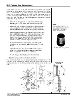
First, make sure your work area is as clean as possible. You will be
handling all components of the center pin and they must be kept as
free of contaminants as possible. Once you open the seals and install
them into the glands, make every effort to get the glands onto the
post as soon as possible. Otherwise, the Teflon seals may absorb too
much moisture from the air. (See Nomenclature illustration in bottom
right corner of pages 7.0 and 7.1.)
Attach the mounting plate to the center pin post (“U”). Apply
LOCTITE
®
242 to the 1/2" x 2" bolts and torque to 100 ft-lb.
Fasten the center pin post to a workbench (or hold it carefully in
a vise, taking great care to protect it from possible damage)
and lubricate the bottom of the post using a high grade grease.
Slide the guide (P/N 8000-1552) onto the center pin post. Care-
fully install the lower gland (“D”) onto the center pin post. Take
great care not to damage any of the high pressure seals in-
stalled earlier. You may need to gently force the gland down
onto the post. If this is the case, use a wooden block and a
dead blow hammer to avoid damaging the gland.
Once you have the lower gland in place, remove the guide
(P/N 8000-1522) and carefully install the top gland (“C”) onto
the post.
Lubricate with grease the upper end of the center pin post.
Again, if the gland doesn’t slide on easily, use a dead blow
hammer and block to assist with the installation.
Now that the glands are in place, install the stop block.
Note!
Do not use LocTite on the 3/8" x 7/8" bolts!
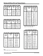
You can double-check your work by checking the rolling torque of the
assembly once complete. It should not take more than a 125 ft-lb.
maximum torque to start moving the outer glands on the center pin
post.
8000-1552 Center pin Guide
Note!
Use the custom-designed guide
(PIN 8000-1552) on the top of the
post which provides a smooth
step from the 3" end to the 5"
end of the center pin post.
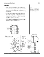
CENTER PIN PACKING
SEAL POSITIONS
Содержание XL4000
Страница 2: ......
Страница 73: ......
Страница 76: ... 5MP ...
Страница 145: ......
Страница 146: ......
Страница 151: ...From No 296020 2 97 4 FIGURE 4 FIGURE 5 FIGURE 3 IV Saving Charge and Pilot Pressure continued ...
Страница 160: ......
Страница 161: ......
Страница 162: ......
Страница 175: ......
Страница 176: ......
Страница 177: ......
Страница 178: ......
Страница 192: ......
Страница 193: ......
Страница 194: ......
Страница 207: ......
Страница 208: ......
Страница 210: ...500P ...
Страница 229: ......
Страница 230: ......
Страница 245: ......
Страница 246: ......
Страница 247: ......
Страница 248: ......
Страница 265: ......
Страница 266: ......
Страница 267: ......
Страница 268: ......
Страница 280: ......
Страница 281: ......
Страница 282: ......
Страница 297: ......
Страница 298: ......
Страница 299: ......
Страница 300: ......
Страница 301: ......
Страница 302: ......
Страница 303: ......
Страница 304: ......
Страница 305: ...GRADALL h y d r a u l i c e x c a v a t o r s XL 4000 5000 CENTER PIN REBUILD Form No 20026 Part No 2460 4164 ...


