VI. Filtration and Cooling Circuit
Filtration
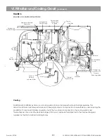
XL 4200 & 5200 SERIES EXCAVATORS use 6 filters to condition and cleanse hydraulic fluid. These filters are
located in the reservoir area and the engine compartment.
See Figure 8
for filter locations and
Figure 9
for filtration and cooling circuit.
Suction Screen (100 mesh)
Mounted inside reservoir on outlet line to pump.
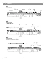
See Figure 6
Prevents foreign objects from entering pump
intakes. When draining reservoir for routine oil changes, remove & inspect this screen. Replace if contaminated.
Breather (10 micron)
Mounted in the engine compartment.
See Figure 8
Allows air to escape when reservoir pressure is above 10 PSI.
Allows air to enter the reservoir when pressure is below 0.3 PSI vacuum. Low air pressure (6 PSI) warning switch
located in dump tube and monitor in operators cab. Replace when low pressure warning light stays on. Replace
filter element whenever other hydraulic system filter elements are replaced.
Recirculation Return Filter (8 micron)
Mounted in engine compartment.
See Figure 8
Reconditions hydraulic fluid received from the recirculation pump
whenever the engine is running. Equipped with a 25 PSI relief valve which allows fluid to bypass whenever this
value is exceeded. A mechanical pressure gauge and an electrical switch warns of high filter pressure. Replace
the filter element whenever high pressure warning devices consistantly read high.
Swing Suction Filter (8 micron)
Mounted in engine compartment.
See Figure 8
Reconditions hydraulic fluid received from the recirculation filter.
Has No bypass features. Delivers fluid to the intake port of the swing pump. Equipped with a mechanical gauge
and an electrical switch to warn of low filter pressure. Replace filter element anytime the mechanical gauge so
indicates.
Pilot Filter (10 micron)
Mounted inside engine compartment.
See Figure 8
Equipped with a pop-up filter condition indicator. Whenever
red color shows, the element must be changed. Will show bypass whenever fluid is under 100 F. Receives fluid
from 6.6 GPM pilot pump. Filters all pilot circuit fluid.
Reservoir Return Filter (10 micron)
Mounted in main return line, inboard side of reservoir.
See Figure 6
Reconditions hydraulic fluid returning from
main control valve assemplies. No oil is supplied to this filter unless the control valves are activated. Equipped
with a magnet, 15 PSI bypass valve, and an electrical bypass indicator.
See Figure 7
Filter element should be
changed if the warning light comes on with fluid temperature @ 100°F. After element change, ensure all seals
are correctly placed whenever cover is reinstalled and tightened.
For location of the filters in the hydraulic system.
See Figure 9
10
Form No. 29704
NOTE!
NOTE!
NOTE!
NOTE!
NOTE!
1.
2.
3.
4.
5.
6.
Содержание XL4000
Страница 2: ......
Страница 73: ......
Страница 76: ... 5MP ...
Страница 145: ......
Страница 146: ......
Страница 151: ...From No 296020 2 97 4 FIGURE 4 FIGURE 5 FIGURE 3 IV Saving Charge and Pilot Pressure continued ...
Страница 160: ......
Страница 161: ......
Страница 162: ......
Страница 175: ......
Страница 176: ......
Страница 177: ......
Страница 178: ......
Страница 192: ......
Страница 193: ......
Страница 194: ......
Страница 207: ......
Страница 208: ......
Страница 210: ...500P ...
Страница 229: ......
Страница 230: ......
Страница 245: ......
Страница 246: ......
Страница 247: ......
Страница 248: ......
Страница 265: ......
Страница 266: ......
Страница 267: ......
Страница 268: ......
Страница 280: ......
Страница 281: ......
Страница 282: ......
Страница 297: ......
Страница 298: ......
Страница 299: ......
Страница 300: ......
Страница 301: ......
Страница 302: ......
Страница 303: ......
Страница 304: ......
Страница 305: ...GRADALL h y d r a u l i c e x c a v a t o r s XL 4000 5000 CENTER PIN REBUILD Form No 20026 Part No 2460 4164 ...

