Part No. 2460-4164
5.0 C
ENTER
P
IN
R
EMOVAL
Note!
The center pin assembly is held
in place by 4 bolts (5/8" standard
thread). Each bolt is equipped
with a lock nut to prevent it from
working loose during normal op-
erations.
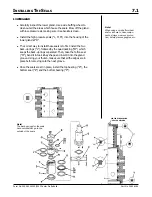
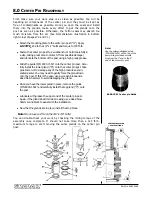
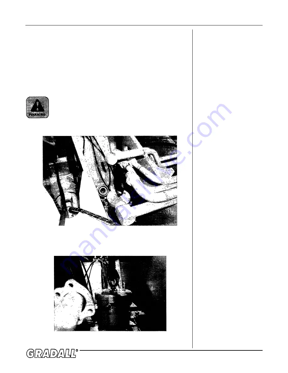
Remove the top cap, allowing the stabilizer bar to be removed. At this
point, a lifting device capable of lifting 300 lbs. may be attached to
the top of the center pin assembly. There is a threaded hole in the
middle of the pin post which accepts a lifting eye. With the lifting
device in place to support the weight, unbolt the center pin assembly
from its mounts. The assembly may now be removed, but you will have
to turn it as you withdraw it through the top. Once you have cleared
the boom cradle area, set the assembly on an appropriate work bench
where it may be cleaned and prepared for disassembly.
During these operations, make sure that you are not
lifting the assembly over anyone’s head!
Содержание XL4000
Страница 2: ......
Страница 73: ......
Страница 76: ... 5MP ...
Страница 145: ......
Страница 146: ......
Страница 151: ...From No 296020 2 97 4 FIGURE 4 FIGURE 5 FIGURE 3 IV Saving Charge and Pilot Pressure continued ...
Страница 160: ......
Страница 161: ......
Страница 162: ......
Страница 175: ......
Страница 176: ......
Страница 177: ......
Страница 178: ......
Страница 192: ......
Страница 193: ......
Страница 194: ......
Страница 207: ......
Страница 208: ......
Страница 210: ...500P ...
Страница 229: ......
Страница 230: ......
Страница 245: ......
Страница 246: ......
Страница 247: ......
Страница 248: ......
Страница 265: ......
Страница 266: ......
Страница 267: ......
Страница 268: ......
Страница 280: ......
Страница 281: ......
Страница 282: ......
Страница 297: ......
Страница 298: ......
Страница 299: ......
Страница 300: ......
Страница 301: ......
Страница 302: ......
Страница 303: ......
Страница 304: ......
Страница 305: ...GRADALL h y d r a u l i c e x c a v a t o r s XL 4000 5000 CENTER PIN REBUILD Form No 20026 Part No 2460 4164 ...


