Form No. 29625 2/97
XL 5210 HYDRAULIC PRESSURE
SETTING MANUAL
(SUPPLEMENTAL PRESSURE)
Assemble two sets of GRADALL gauge hoses from test kit with a connector. On one set of hoses, place a
10,000 psi gauge. Place a 1,000 psi gauge on the other set. Route both sets of hoses across machine so that
both gauges may be laid on the cradle stop at the front of the frame on the left hand side of the cab. Connect the
hose with the high pressure gauge to the outside test port of the swing pump. Remove the plug that is between
the two high pressure test ports. Install adapter (8656-1311) and test port (7713-3089) in place of the plug.
Attach the hose with the low pressure gauge to this added test port. Start the engine and allow it to run at a
low RPM. Go to the gauge end of the hoses, remove the gauges and allow air to bleed out of the hoses.
Catch any oil in an approved container to prevent oil spills. After air is purged, reinstall gauges and clean up
any spillage.
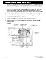
Place tool firmly on ground, run engine at full RPM, then meter the right hand joystick for right hand swing.
Observe the gauges for when the low pressure gauge rises to 90 psi, swing pressure on the high pressure gauge
should rise to 500 - 550 psi. This is the swing begin point. Adjust the inside screw on the pump control to achieve
proper begin pressure.
See Figure 1.
NOTE!
This adjustment affects swing begin pressure; it does not affect the pilot signal to the pump.
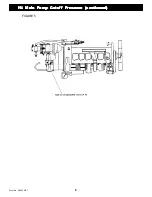
Move hose with high pressure gauge to the inside test port, bleed air from this hose after moving it. Repeat this
procedure, except use left hand swing. Adjustments are made to the outside adjustment screw.
See Figure 1.
After adjustments are made, check operation and metering of swing circuit. Also check the maximum torque setting
(see hydraulic testing and adjusting manual).
I. Pump Adjustment and Setup
I. Pump Adjustment and Setup
I. Pump Adjustment and Setup
I. Pump Adjustment and Setup
I. Pump Adjustment and Setup
This information is to be used for adjustment and setup of the main and swing pumps. In most situations, the
pumps will not need to have the following settings checked or altered. Consult with GRADALL before altering
pump settings.
All other pressures must be checked using the XL 5210 Hydraulic Pressures Setting Manual before making any
checks of pump settings. The procedures in this Manual will require the same tools. Additional gauge hoses — two
7713-3259 hoses and one 7713-4198 union — will be required. These can be removed from another gauge kit, or
ordered separately.
If any pump adjustment screws are altered, a new seal cap must be installed. Two sizes of cap are used on
GRADALL XL SERIES excavators. Small blue caps are port number 8093-4459; and large blue caps are part number
8093-4460.
This procedure covers XL 5210 machines. Each step will note pressures for specific models. If you are servicing a
machine other than what is listed, please consult with GRADALL for correct settings.
II. Swing Pump Begin Point
II. Swing Pump Begin Point
II. Swing Pump Begin Point
II. Swing Pump Begin Point
II. Swing Pump Begin Point
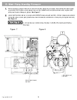
The Swing Pump Begin Point adjustment controls the point that the swing pump comes on stroke in relation to
joystick input pressure. This should only be adjusted if the machine exhibits problems with swing start, or pulsing
while swinging. This also should be adjusted if someone has tampered with the swing pump begin point screws.
Reseal swing pump begin point screws after adjustment.
1.
2.
3.
4.
1
Содержание XL4000
Страница 2: ......
Страница 73: ......
Страница 76: ... 5MP ...
Страница 145: ......
Страница 146: ......
Страница 151: ...From No 296020 2 97 4 FIGURE 4 FIGURE 5 FIGURE 3 IV Saving Charge and Pilot Pressure continued ...
Страница 160: ......
Страница 161: ......
Страница 162: ......
Страница 175: ......
Страница 176: ......
Страница 177: ......
Страница 178: ......
Страница 192: ......
Страница 193: ......
Страница 194: ......
Страница 207: ......
Страница 208: ......
Страница 210: ...500P ...
Страница 229: ......
Страница 230: ......
Страница 245: ......
Страница 246: ......
Страница 247: ......
Страница 248: ......
Страница 265: ......
Страница 266: ......
Страница 267: ......
Страница 268: ......
Страница 280: ......
Страница 281: ......
Страница 282: ......
Страница 297: ......
Страница 298: ......
Страница 299: ......
Страница 300: ......
Страница 301: ......
Страница 302: ......
Страница 303: ......
Страница 304: ......
Страница 305: ...GRADALL h y d r a u l i c e x c a v a t o r s XL 4000 5000 CENTER PIN REBUILD Form No 20026 Part No 2460 4164 ...


