background image

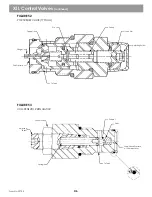
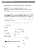
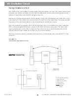
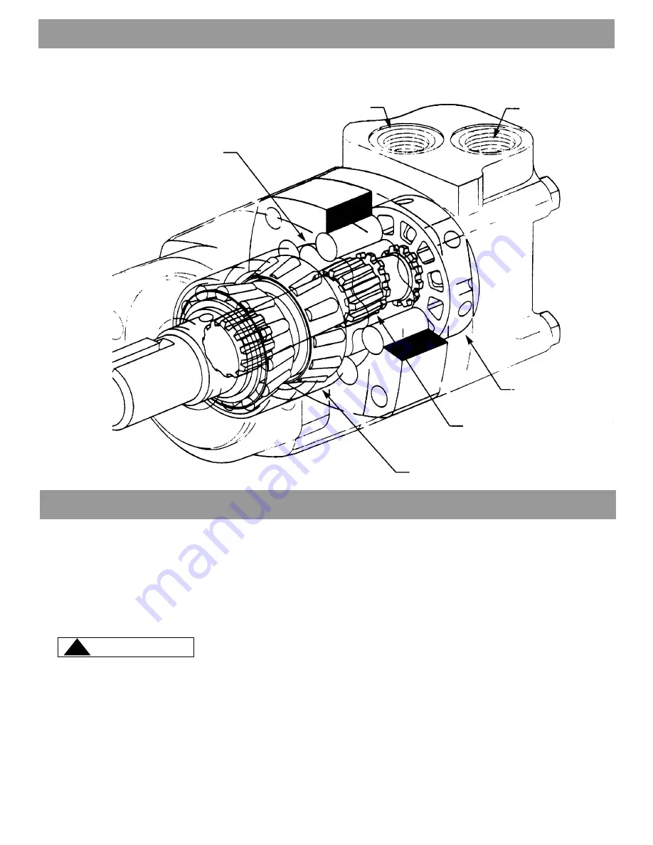
FIGURE 64

TILT MOTOR

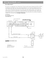
Boom Circuit

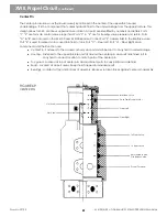
The boom circuit extends and retracts the telescope boom to any point within the boom travel range. This is
accomplished by the use of a special boom cylinder configuration. The cylinder uses a regenerative hydraulic fluid
circuit to extend the boom and a non regenerative (standard) hydraulic fluid circuit to retract the boom. Boom
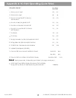
cycle times are shown in “Appendix B” (XL 4100) or “Appendix C” (XL 5100) of this manual.

Never run the boom faster than specification. This will cause system overheating,
seriously affecting machine performance.

The boom cylinder rod is fastened to the back of the boom cradle. The boom cylinder barrel is fastened to the
telescope boom. When pressurized the barrel extends and retracts. The cylinder receives fluid internally through a
gland mounted to the rear of the cylinder rod. The boom cylinder stop (when retracting) uses a plastic cushion
that is located in the base end cylinder head. Holes in the cylinder rod provide some hydraulic cushioning at the
end of the extend stroke.

Refer to

 XL 4000/5000 Upperstructure Mechanical Adjustments & Repair Manual

 (Form 29604) for cylinder

and cylinder component installation and removal.

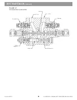
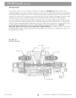
XVI. Tilt Circuit

 (continued)

XVII. Boom Circuit

Geroler Star

“B” Port

“A” Port

Disc Valve

Motor Shaft Drive And

Valve Drive

Motor Shaft And Bearings

WARNING

!

Form No. 29703

56

Содержание XL4000

Страница 1: ...CAVATOR TECHNICAL MANUAL GRADALL 406 Mill Avenue S W New Philadelphia OH 44663 USA Telephone 330 339 2211 Fax 330 339 3579 VOLUME 2 2460 4144 XL4000 Starting S N 0415225 0428225 XL5000 Starting S N 0518110 0526110 ...

Страница 2: ......

Страница 3: ...H Y D R A U L I C E X C A V A T O R S GRAD GRAD GRAD GRAD GRADALL ALL ALL ALL ALL Form No 29703 Issued 8 98 ...

Страница 4: ...n to expect it Make sure each of you knows where the other is at all times Be sure you understand all steps of the procedure before testing and or adjusting any circuit Follow the procedure carefully Always wear safety glasses when performing testing and adjusting procedures Clean up oil spills immediately Slippery surfaces can cause serious accidents Always make sure engine RPM is correct before ...

Страница 5: ...y specified hydraulic fluid in the Gradall Use of fluids other than those which meet specifications will seriously damage the hydraulic components resulting in expensive failure or machine downtime Approved fluids are Hydraulic Oil M bilfluid 424 or Citgo Tractor Hyd Fluid 33310 Fire Resistant Fluid Quaker Chemical Quintolubric 822 300 Do Not use any other fluid without first receiving approval fr...

Страница 6: ... equipped with a circuit test port The use of tubing also assists with system heat disapation Replacement tubing should be stored in a dry atmosphere and must be free of rust and contaminants Clamping Hose and tubing runs are protected from unwanted movement by clamping Clamps should be sized correctly for the hose or tube on which it is used Multiple hose tubing clamps are available and their use...

Страница 7: ...nd of the cylinder Internal Cylinder Rod Function is to carry hydraulic fluid to the barrel end of the cylinder Location is inside of the cylinder rod Cylinder Gland Function to deliver fluid to selected port in the cylinder Equipped with seals that allow rotation prevents fluid leakage Allows for boom tilt Rod Bearing Location back of the cradle in boom cylinder retainer Function Provide structur...

Страница 8: ...RATIVE MODE Front Machine Rear Hydraulic Pressure from control valve Both sides of piston equal pressure Barrel Movement Results from area differential barrel to rod side of piston FIGURE 4 BOOM CYLINDER STANDARD CYLINDER MODE RETRACT Front Machine Return From Barrel Side Hydraulic fluid Rear Pressure Fluid Return Fluid Pressurized Hydraulic Fluid 6 Form No 29703 ...

Страница 9: ...gure 5 Function Open and close bucket on standard machine Location at end of telescope boom Fastened to telescope boom at barrel end and bucket adapter at rod end Standard hydraulic cylinder ie cylinder rod extends retracts when pressurized Refer to XL 4000 5000 Upperstructure Mechanical Adjustment Repair Manual Form 29604 for removal and installation instructions Re pack kits available l l l l l ...

Страница 10: ...ard hydraulic cylinder ie cylinder rod extends retracts when pressurized Adjustable rod end Re pack kits available l l l l l l FIGURE 6 STEERING CYLINDER Tie Rod Nut Cylinder Base Pin Clip Tie Rod O Ring Piston Tube Back up Ring Piston Nut O Ring Pipe Plug Tie Rod Nut Clevis Pin Cylinder Head Tie Rod Nut Back up Ring Clevis Cap Screw Pin Clip Clevis Pin Clevis Nut Rod Wiper O Ring O Ring 8 Form No...

Страница 11: ...s frame Quantity 2 Standard hydraulic cylinder ie cylinder rod extends and retracts when pressurized Re pack kits available FIGURE 7 OSCILLATION LOCK CYLINDER l l l l l Clamp Assembly Clamp Hex HD Cap Screw Cylinder Head Tube Assembly Cylinder Head Tube Hex Lock Nut Piston Head Assembly Piston Piston Ring O ring Piston Rod Retaining Ring Retaining Ring Lockwasher Seal Ring Rod Wiper O Ring Back up...

Страница 12: ...cess covers are designed into the reservoir These allow entrance into the internal areas to facilitate cleaning of normal sediment build up Air Breather A pressurized breather vents air to the atmosphere once it exceeds 10 PSI See Figure 10 The reservoir is pressurized by the machine air system The reservoir pressure is set of 6 8 PSI This forces hydraulic fluid into the pump supply lines An elect...

Страница 13: ...NDICATORS FIGURE 8 RESERVOIR 9 Suction Screen 5 Accessibility 1 3 4 Capacity Heat Dissipation Turbulence 6 Air Breather Located in Engine Compartment See Figure 10 8 Return Filter 2 Capacity Check 7 Drain Plug 11 XL 4100 XL 5100 HYDRAULIC SYTEM OPERATIONS MANUAL Form No 29703 ...

Страница 14: ...r this value is exceeded A mechanical pressure gauge and an electrical switch warns of high filter pressure Replace the filter element whenever high pressure warning devices consistantly read high Swing Suction Filter 8 micron Mounted in engine compartment See Figure 10 Reconditions hydraulic fluid received from the recirculation filter Has No bypass features Delivers fluid to the intake port of t...

Страница 15: ...urn Filter Gauge Pop Up Filter Indicator Pilot Filter Reservoir Air Pressure Gauge Air Breather Pilot Pump Recirculation Pump Air Pressure Drain Thermal Bypass Valve Pressure Reducing Valve Pilot Manifold NOTE NOTE NOTE NOTE NOTE For location of the filters in the hydraulic system See Figure 11 13 XL 4100 XL 5100 HYDRAULIC SYTEM OPERATIONS MANUAL Form No 29703 ...

Страница 16: ...er oil cooler if the hydraulic fluid is above 120 F Equipped with a 70 PSI relief valve protects the heat exchanger oil cooler l l l l l Cooling XL 4100 and XL 5100 Excavators use a cooling system to maintain proper hydraulic fluid temperature This allows for optimum machine performance by keeping hydraulic components at peak efficiency and reducing the possibility of component binding caused by h...

Страница 17: ...Located in front of the engine radiator See Figure 12 Keep space between heat exchanger and engine clear of debris Cools hydraulic fluid approximately 100 above ambient temperature Receives fluid from Thermal Bypass Valve Maximum flow through heat exchanger is 20 6 GPM Directs fluid from the heat exchanger to the reservoir filter Replace if system failure is caused by major contamination It is ver...

Страница 18: ... and valve load sensing circuit sending a signal of the highest circuit pressure to the pump These stroking controls read the two pressure signals to change pump displacement as needed and to match pump flow to hydraulic system requirements When controls are not being used the pump goes to standby and maintains enough flow for standby pressure 300 350 PSI See Figure 15 The rotary groups in the mai...

Страница 19: ...3 MAIN PUMP ASSEMBLY TOP CROSS SECTION Outlet A1 Port Pump Case Gearsets Barrel Outlet A2 Port End Cover Swivel Fork Stroking Piston Assembly Inlet Port Lens Input Shaft Piston 17 XL 4100 XL 5100 HYDRAULIC SYTEM OPERATIONS MANUAL Form No 29703 ...

Страница 20: ...he engine at idle speed 800 RPM for 15 seconds all valves in Neutral Stop engine Bleed air from the following Pilot valve loosen hose at pilot shut off valve in the valve module Swing motor slightly loosen working lines on top of motor Swing pump install gauge lines in M5 and M6 test ports to vent Restart engine at idle speed Check swing charge pressure on front port G of swing charge valve Pressu...

Страница 21: ...tool cylinder 5 times allowing the cylinder to bottom on the last cycle Actuate the propel circuit slowly in forward and reverse 5 times carrier must not be in dig mode Sample fluid for cleanliness log Top off hydraulic reservoir Double Pump Assembly 18 19 20 21 22 23 FIGURE 14 PUMP STROKING SYSTEM Primaries Pressure Sense Signal From Valves Valves High Pressure Cutoff Horse Power Control LOad Sen...

Страница 22: ...draulic Pump continued Load Sense Control FIGURE 16 MAIN PUMP Horsepower Control High Pressure Cutoff lnput Shaft Regular Piston Rotary Groups Stroking Piston Swivel Fork Lever Assembly Inlet Port 20 Form No 29703 ...

Страница 23: ...om the suction filter mounted in the engine compartment Charge pressure is handled by a separate shim type relief in the pump case Swing pump controls are mounted on the pump case Two separate valve assemblies are bolted to the pump case The torque control valve receives signals from the pump output ports and the swing joystick Displacement of the swing pump is determined by the machine controls a...

Страница 24: ...echanical Setting Swing Pump Assembly Input Shaft Torque Adjustment High Pressure Anti Cavitation Relief Valves 2 Begin Point Hydraulic Centering Adjustment Torque Control Valve Braking Valve High Pressure Test Port High Pressure Test Port Cushioning Adjustment Pilot Input PressureTestPlug 22 Form No 29703 ...

Страница 25: ...r using a separate outlet ineach section The front outlet is from the 14 GPM section that supplies fluid to the heat exchanger oil cooler and return filter The rear outlet is from the 6 6 GPM section that supplies fluid the pilot system No adjustments are provided for the gear pumps If problems are suspected they can be checked with a flow meter and repaired or replaced if flow is 10 below rated f...

Страница 26: ...ls and swing brake release valve Two joysticks and two foot pedals control machine functions See Figure 24 The boom hoist control curves are different than the swing tool curves All functions except tilt are controlled by hydraulic pilot signals Piloted end caps on each control valve receive the pilot signal Both the valve control curve and spool centering are determined by springs in the end caps...

Страница 27: ...TION X Pilot Circuit continued Reduce 480 PSI pilot circuit pressure to 350 PSI Part of swing motor circuit Inside of counterweight mounting plate on left side of machine FIGURE 23 PRESSURE REDUCING VALVE Swing Charge Valve Relief 380 420 PSI Pressure Reducing Relief 350 PSI Left Side of Machine Low Pressure Pilot Charge Test Port LP Swing Charge Test Port 25 l l ...

Страница 28: ...gs This modulates supply pressure from the P port to one or more of the four working ports on to the valve end caps then to the swing pump It is important to remember that joysticks do not regulate flow they regulate pressure FOOT PEDALS Gradall uses the same pedal valves for travel in the crawlers as well as the truck mounts They are basically the some as the joysticks but only have two pressure ...

Страница 29: ... OPERATIONS MANUAL X Pilot Circuit continued FIGURE 25 JOYSTICK PORTS FIGURE 26 JOYSTICK FIGURE 27 FOOT PEDAL Center Picture Lever Boot Plunger Return Spring Regulating Spring Regulating Spool Push Rod Conrol Springs Return Springs Control Spool 27 ...

Страница 30: ...R2 LI R4 PR PF T P STD GRADALL W AUX HYDRAULICS DECAL P N 8091 3019 DECAL P N 8091 3041 DECAL P N 8091 3042 AUX HYD DECAL P N 8091 3038 PILOT CONTROLLER HOSE DESIGNATION PILOT HOSE CONNECTIONS FIGURE 24 JOYSTICK CONTROL PATTERNS X Pilot Circuit continued Tool Open tool close boom out boom in hoist up swing left hoist down swing right propel reverse propel forward tank pressure TO TC BO BI HU SWL H...

Страница 31: ...ing pump control and motor are completely separate from the machine implement hydraulics This allows Gradall to operate all other hydraulic functions without affecting the swing It is also more efficient by requiring less power and creating less heat in the hydraulic system Only the reservoir is common in the hydraulic system To give precise control of the swing operation the operator has control ...

Страница 32: ...late Rotary Group Port Block Driveshaft Charge Pump Seal Cage Pump Case Piston Thru Drive Pump Mechanical Centering High Pressure Anti Cavitation Relief Valves 2 Swing Pump Assembly Begin point Hydraulic Centering Adjustment Torque Control Valve Braking Valve High Pressure Test Port Input Shaft Pilot Input Pressure Test Plug High Pressure Test Port Torque Adjustment Begin Point Hydraulic Centering...

Страница 33: ...Figure 17 The charge pump relief valve is set at 400 PSI It provides makeup hydraulic fluid for the loop and control fluid to the torque control During normal operation some internal leakage exists in the pump and motor Charge fluid is bled into the low pressure side of the loop to replenish loop fluid that has been lost due to normal internal leakage The high pressure anti cavitation reliefs in t...

Страница 34: ...with a 350 PSI relief valve A check valve isolates the output of the pressure reducing valve from the charge circuit Dump fluid from the valve returns to tank through the pump case When charge circuit pressure drops below relief setting in the pressure reducing valve fluid from the pressure reducing valve provides make up fluid into the charge circuit until the momentary need for extra fluid passe...

Страница 35: ...swing parking broke Note See Figure 35 This view shows the pilot signal shuttle valve and maximum torque control valve This tells the torque control valve direction of swing as selected by the operator and limits maximum torque output by acting on the pilot signal Figure 36 shows pilot orifices These limit oil flow to the relief See Figure 35 Shown are the torque control piston and high pressure s...

Страница 36: ...ing parking brake This view shows the stroking control piston and braking cushioning piston These components perform the function of providing control pressure to stroke the pump when swinging and controls pump clestroke when stopping to provide a cushioned stop FIGURE 37 BRAKING VALVE CUSHIONING VALVE XI Swing Circuit continued Cushioning Adjustment Cushioning Spool To Stroking Control Piston Str...

Страница 37: ...the pump through port 15 This signal shifts a shuttle valve and through internal drillings routes fluid to the torque control piston and to the end of the braking piston At the braking piston the high pressure fluid shifts it to the left and closes off ports X3 from 14 High pressure fluid at the torque control piston works with the spring in the left hand end cap to balance pilot pressure in the r...

Страница 38: ...drops the spring will overcome the pressure and allow the stroking piston to shift more rapidly to neutral This will allow pressure to rise at B port and continue to slow the swinging action Pressure in the pump will also buffer the speed that the swashplate returns to neutral Adjustment of the braking piston will alter the stopping action Turning the screw in will increase spring pressure and inc...

Страница 39: ... to the swing brake The brake starts to release at approximately 70 80 PSI It is fully released at 100 PSI When the swing joystick returns to neutral pilot fluid is cut off to the swing brake Once the upperstructure stops swinging oil is evacuated from the brake pressure line though an office valve in the swing brake release valve to tank The office valve holds sufficient pressure in the broke cir...

Страница 40: ...ence valve shifts to a neutral position Pressure fluid from the brake is directed to tank The fluid flows through a predetermined sized orfice valve which restricts flow until the upperstructure stops swinging This restricted flow keeps the swing parking brake pressurized until approximately 3 seconds after swing stops The swing brake release valve contains three cartridges They are Shuttle Valve ...

Страница 41: ...See Figure 44 A smaller control valve bank with travel and boom valves is located behind the large bank See Figure 45 All valves are pressure compensated with a load sense system See Figure 45 Each section has a compensator spool a primary shuttle between the work ports and a secondary shuttle tied into the pump load sense system See Figure 46 FIGURE 42 MAIN CONTROL VALVE BANKS SHOWN WITHOUT TUBIN...

Страница 42: ...Form No 29703 FIGURE 43 BUCKET HOIST VALVE BANK ALL MODELS TYPICAL XII Control Valves continued Bucket Hoist Boom Tilt Diverter Outlet Clipper Relief Inlet Load Sense Port To Rear Valve Bank 40 ...

Страница 43: ... FIGURE 44 BOOM PROPEL VALVE BANK XL 4100 AND XL 5100 FIGURE 45 LOAD SENSING CIRCUIT Propel Boom Clipper Relief Inlet Load Sense Port from Front Valve Bank Outlet Load Sense To Pump Secondaries Primaries Hoist Valve Boom Valve 0 60 GPM 0 60 GPM 2000 RPM Rated PUMP DRIVE Secondaries Primaries 41 ...

Страница 44: ...ompensator determines which is the higher pressure valve bank The bucket and hoist valve bank has priority on fluid from one pump section In low flow conditions the diverter forces fluid from one pump section into the bucket and hoist bank The diverter meters fluid from the two pump sections to match flow requirements in each valve bank It is possible through the diverter for both pump sections to...

Страница 45: ...pool These solenoids work with pilot fluid directed through passageways into electric end caps The tilt valve uses proportional solenoids the auxiliary valve uses simple on off solenoids Some end caps have stroke limiters that control function speed Hoist up boom in out and travel all have adjustable stroke limiters If a machine has an auxiliary hydraulic circuit this valve is also equipped with s...

Страница 46: ...AD CHECK POSITION XII Control Valves continued FIGURE 49 COMPENSATOR SPOOL OPERATION FLOW POSITION Inlet Pressure Compensate Pressure Port Pressure Tank Pressure B Port A Port Inlet Pressure Compensate Pressure Port Pressure Tank Pressure B Port A Port 44 ...

Страница 47: ...CTION FIGURE 51 VALVE BANK INLET COVER TYPICAL Primary Shuttle Under Rear Piloted End Cap To Valve B Port To Valve A Port Secondary Shuttle Bottom of Control Valve Body Compensator Primary Shuttle Pump Valve Load Sense Port Pump Valve Load Sense Port Secondary Shuttle Clipper Relief Torque 50 ft lb Torque 50 ft lb Load Sense Port 45 INLET OUTLET ...

Страница 48: ...tinued FIGURE 52 PORT RELIEF VALVE TYPICAL FIGURE 53 COMPENSATOR REGULATOR Pin Spring Poppet Lock Nut Adjusting Screw Plunger Port Pressure To Tank Poppet Seat Adjusting Screw Load Sense Pressure At Compensator Spring To Tank Lock Nut 46 ...

Страница 49: ...s to increase According to fluid flow requirements in the valve bank fluid causing such an increase in pressure will be diverted to the other valve bank This allows simultaneous function Fluid flow within this circuit can occur in any direction Fluid from the rear valve bank can be sent to the front valve bank fluid from the front valve bank can be sent to the rear valve bank See Figure 56 In low ...

Страница 50: ...iverter Valve Circuit continued 48 Form No 29703 A Port GRADALL P N 8093 4356 Cover B Port GRADALL P N 8093 4350 Plug Retainer DummySpool Spring Diverter Diverter Valve Bucket Valve Hoist Valve HOIST BUCKET VALVE BANK ASSEMBLY Propel Valve Boom Valve MainPump BOOM VALVE BANK ASSEMBLY ...

Страница 51: ...nder through a series of hoses and tubes Hoses between the Main Boom and Telescope Boom are captured in an assembly called the hose trough Refer to XL 4000 5000 Upperstructure Mechanical Adjustment Repair Manual Form 29604 for information on hose layout in this assembly As the telescope boom extends and retracts tool cylinder hoses inside the trough roll forward or backward Lubricating these hoses...

Страница 52: ...nal shifts the valve spool and the compensator meters fluid to the spool The spool then routes fluid to the bucket cylinder The valve load sense system controls compensator shift and signals the pump load sense system Bucket close speed is controlled by valve spool notches When this circuit is bottomed the regulator opens and allows the compensator to shift cutting off fluid to the bucket circuit ...

Страница 53: ...100 5100 HYrDARAULIC SYSTEM OPERATIONS MANUAL Form No 29703 XIV Tool Circuit continued FIGURE 59 TOOL BUCKET VALVESECTION Port Relief A Port Spool B Port Port Relief Section Regulator Spring Compensator 51 ...

Страница 54: ...ed to the main frame and boom cradle Whenever the cylinder rods retract the boom lowers Whenever the cylinder rods extend the boom raises Main pump fluid is directed to both cylinders simultaneously through large hydraulic fluid tubes located at the rear of the cylinders These tubes are fed from port A or B of the control valve Return fluid flows through the opposite unpressurized port XV Hoist Ci...

Страница 55: ...uit until pump output pressure is higher than circuit pressure If this circuit stalls while hoisting up the regulator opens and allows the compensator to shift cutting off fluid to the hoist circuit until pressure drops below the regulator setting Port relief on hoist up rear port protects against external loads Port relief on hoist down front port prevents excess down pressure and affects stabili...

Страница 56: ... 64 The tilt motor is fastened to a mechanical transmission located at the back of the boom cradle The motor drives this transmission clockwise or counter clockwise when pressurized The transmission drives a tilt bearing mounted to the main boom and boom cradle Refer to XL 4000 5000 Upperstructure Mechanical Adjustments Repair Manual Form 29604 for additional information on the mechanical portion ...

Страница 57: ...he right hand joystick is actuated the electrical signal shifts the solenoid spool which sends a pilot signal that shifts the valve spool The compensator meters fluid to the spool which then routes fluid to the tilt motor The valve load sense system controls compensator shift and signals the pump load sense system Tilt speed is controlled by the valve spool metering returning fluid from the motor ...

Страница 58: ... cylinder rod is fastened to the back of the boom cradle The boom cylinder barrel is fastened to the telescope boom When pressurized the barrel extends and retracts The cylinder receives fluid internally through a gland mounted to the rear of the cylinder rod The boom cylinder stop when retracting uses a plastic cushion that is located in the base end cylinder head Holes in the cylinder rod provid...

Страница 59: ...The telescope boom retracts Refer to Figure 4 Figure 65 for a cutaway view of the boom cylinder and fluid flow of this Circuit in the cylinder FIGURE 65 BOOM RETRACT CIRCUIT NON REGENERATIVE XVI Tilt Circuit continued Cylinder Gland 57 Boom Cylinder BaseTilt Internal Cylinder Rod Tube Cylinder Rod Boom Cylinder Barrel MOVEMENT Exhaust Area Pressurized Area Pressurized Area Cylinder Piston BoomC V ...

Страница 60: ... Since rod side fluid is joined to the pump fluid both sides of the cylinder are pressurized The piston area in the barrel is larger than the area in the rod side of the cylinder This imbalance of area forces the boom to extend See Figure 3 Figure 66 FIGURE 66 BOOM EXTEND CIRCUIT REGENERATIVE XVII Boom Circuit continued Form No 29703 Cylinder Gland Internal Cylinder Rod Tube Cylinder Rod CYLINDER ...

Страница 61: ...he rear port relief protects against external loads the front port relief controls boom out pressure When the rear end cap is pressurized for boom out the spool immediately shifts to full regeneration In regeneration both sides of the cylinder run at or near equal pressure Oil does not return to the reservoir during boom out operation The maximum flow rate out of the A front port is 48 GPM pump 54...

Страница 62: ...ed through the drive shaft and axles to the rear wheels On 6x6 units the front wheels are also driven in remote if the transfer case is engaged Orifice check valves on the travel motor maintain back pressure in the motor while travelling to prevent freewheeling down a grade An air chamber on the truck chassis keeps the clutch disengaged whenever the machine is in the remote control mode The travel...

Страница 63: ...rain fluid to tank Port C Steer Left Port A Steer Right Main components and their function are Center Pin Fastened to the crawler carbody Has ports machined in it to carry fluid to undercarriage Housing Fastened to the upperstructure and fits around the center pin Has ports machined in it to carry fluid to correct location to match ports of the center pin Top gland Located at top of center pin Has...

Страница 64: ...pedal is actuated the pilot signal shifts the valve spool and the compensator meters fluid to spool The spool then routes fluid to the travel motor The valve load sense system controls compensator shift and signals the pump load sense system Travel speed is controlled by preset stroke limiters in each end cap When travelling port reliefs limit maximum pressure in the work circuit The valve motor s...

Страница 65: ...d prevent the cylinder from bottoming mechanically The steering cylinder is connected to the right side of the chassis frame and the steering axle Fluid for the steering cylinder is supplied by the Recirculating Pump Fluid from the pump flows to the Priority Flow Regulator in the Pilot Manifold See Figure 71 The priority flow regulator diverts a portion of the 14 GPM from the pump delivering it to...

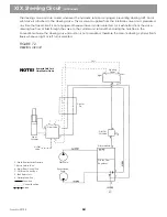
Страница 66: ...e conventional mode the steering valve air portion is not pressurized therefore the remote steering cylinder floats freely whenever right or left turn is selected FIGURE 72 STEERING CIRCUIT XIX Steering Circuit continued Steer Cylinder Form No 29703 64 Left Left Air Pilot Valve Steer Valve Center Pin Steering Pedal Pilot Cut Off Valve Pilot Manifold Priority Flow Regulator PilotPump Recirculation ...

Страница 67: ...e travel pedal is engaged pilot air from the interface valve to the oscillation lock valve is exhausted With no air pressure against the poppet a minimum of 5 PSI from the return circuit unseats the check valve opening all fluid ports to each other The fluid is now free to flow from the rod side to the barrel side of each cylinder as the front axle oscillates The cylinders now act as shock absorbe...

Страница 68: ...ed while using auxiliary hydraulics relief valves open to protect the circuit from excessive pressure The valve spool allows a maximum flow rate of 40 GPM out of both work ports Fluid is routed to the end of the boom through a hose trough This trough consists of guide plates a roller springs and a carriage it is located at the rear of the main boom Normally two hoses are in this trough If optional...

Страница 69: ...system makes it is necessary to use a GRADALL hydraulic kit Use of after market kits will prevent the proper operation of the pump load sense system resulting in poor no hydraulic function For additional kit information contact GRADALL Parts Marketing FIGURE 75 AUXILIARYVALVESECTION Port Relief B Port Spool A Port Port Relief Compensator 67 Tankand Pressure Ports for Electric End Cap Stroke Limite...

Страница 70: ...25 8 ORS Face Seal Tube Hose To Fitting SAE DASH SIZE 4 6 8 10 12 16 20 24 TUBE SIDE ASSEMBLY TORQUE FT LBS 18 1 27 2 40 2 63 3 90 4 120 8 140 8 165 8 Aluminum Material Ports Use 50 of the Steel Torque Valve NOTE SAE Fittings Straight Adjustable THREAD SIZE 5 16 24 3 8 24 7 16 20 20 9 16 18 16 7 8 14 1 1 16 12 1 3 16 12 1 5 16 12 1 5 8 12 1 7 8 12 2 12 SAE DASH SIZE 2 3 4 5 6 8 10 12 14 16 20 24 3...

Страница 71: ...lt 220 Max Clockwise Counter clockwise 6x4 6x6 Propel Speed 2 03 MPH Time for 100ft Lo Lo Gear St d 6BTA 5 9 Chassis Time for 100 ft LO Lo Gear Opt 6CTA 8 3 Chassis Appendix B XL 4100 Operating Cycle Times Adjust propel valve compensator spool limiter to change propel speed 69 SECONDS MIN MAX 5 0 5 5 6 0 6 5 1 8 3 0 3 0 3 6 2 4 3 0 1 2 2 4 1 8 2 4 3 6 4 2 7 8 9 0 3 0 3 6 7 8 10 8 Fwd 30 0 36 0 Rev...

Страница 72: ...ops Tilt 220 Max Clockwise Counter clockwise 6x4 6x6 Propel Speed 2 2 MPH Time for 100 Lo Lo Gear SECONDS MIN MAX 5 0 5 5 7 0 7 5 1 8 3 0 2 6 4 2 3 0 3 6 1 2 2 4 2 4 3 0 4 8 6 0 9 6 10 8 3 0 3 6 7 8 10 8 Fwd Rev 28 0 34 0 1900 RPM 1 2 3 4 5 6 7 8 9 10 11 12 A Main Pump Power Setting Engine drawdown when combining Swing Hoist up Boom out Machine moving with full bucket Note 13 Appendix C XL 4100 Op...

Страница 73: ......

Страница 74: ...ULIC SYSTEM OPERATIONS MANUAL Form No 29703 GRAD GRAD GRAD GRAD GRADALL ALL ALL ALL ALL Hydraulic Excavators 406 Mill Ave SW New Philadelphia Ohio 44663 USA Phone 330 339 2211 Fax 330 339 8468 www gradall com 1998 GRADALL ...

Страница 75: ...XL 4200 XL 5200 HYDRAULIC SYSTEM OPERATIONS MANUAL GRAD GRAD GRAD GRAD GRADALL ALL ALL ALL ALL H Y D R A U L I C E X C A V A T O R S Form No 29704 Issued 8 98 ...

Страница 76: ... 5MP ...

Страница 77: ...ect from the other and when to expect it Make sure each of you knows where the other is at all times Be sure you understand all steps of the procedure before testing and or adjusting any circuit Follow the procedure carefully Always wear safety glasses when performing testing and adjusting procedures Clean up oil spills immediately Slippery surfaces can cause serious accidents Always make sure eng...

Страница 78: ...uit Hydraulic fluid Use only specified hydraulic fluid Use of fluids other than those which meet specifications will seriously damage the hydraulic components resulting in expensive failure or machine downtime Approved fluids are Hydraulic Oil M bilfluid 424 or Citgo Tractor Hyd Fluid 33310 Fire Resistant Fluid Quaker Chemical Quintolubric 822 300 Do Not use any other fluid without first receiving...

Страница 79: ...e GRADALL is equipped with a circuit test port The use of tubing also assists with system heat disapation Replacement tubing should be stored in a dry atmosphere and must be free of rust and contaminants Clamping Hose and tubing runs are protected from unwanted movement by clamping Clamps should be sized correctly for the hose or tube on which it is used Multiple hose tubing clamps are available a...

Страница 80: ...rrel end of the cylinder Location is inside of the cylinder rod Cylinder Gland Function to deliver fluid to selected port in the cylinder Equipped with seals that allow rotation prevents fluid leakage Allows for boom tilt Rod Bearing Location back of the cradle in boom cylinder retainer Function Provide structural attachment of the boom cylinder rod to the boom Allows the boom cylinder rod to rota...

Страница 81: ... CYLINDER REGENERATIVE MODE Front Machine Rear Hydraulic Pressure from control valve Both sides of piston equal pressure Barrel Movement Results from area differential barrel to rod side of piston FIGURE 4 BOOM CYLINDER STANDARD CYLINDER MODE RETRACT Front Machine Return From Barrel Side Hydraulic fluid Rear Pressure Fluid Return Fluid Pressurized Hydraulic Fluid ...

Страница 82: ...le XL 4200 XL 5200 HYDRAULIC SYTEM OPERATIONS MANUAL Form No 29704 7 Tool Cylinder Function Open and close bucket on standard machine Location at end of telescope boom Fastened to telescope boom at barrel end and bucket adapter at rod end Standard hydraulic cylinder ie cylinder rod extends retracts when pressurized Refer to XL 4000 5000 Upperstructure Mechanical Adjustment Repair Manual Form 29604...

Страница 83: ... are designed into the reservoir These allow entrance into the internal areas to facilitate cleaning of normal sediment build up Air Breather A pressurized breather vents air to the atmosphere once it exceeds 10 PSI See Figure 6 and 8 The reservoir is pressurized by the machine air system The reservoir pressure is set of 6 8 PSI This forces hydraulic fluid into the pump supply lines An electrical ...

Страница 84: ...INDICATORS FIGURE 6 RESERVOIR 9 Suction Screen 5 Accessibility 1 3 4 Capacity Heat Dissipation Turbulence 6 Air Breather Located in Engine Compartment See Figure 8 8 Return Filter 2 Capacity Check 7 Drain Plug XL 4200 XL 5200 HYDRAULIC SYTEM OPERATIONS MANUAL Form No 29704 9 ...

Страница 85: ...n electrical switch warns of high filter pressure Replace the filter element whenever high pressure warning devices consistantly read high Swing Suction Filter 8 micron Mounted in engine compartment See Figure 8 Reconditions hydraulic fluid received from the recirculation filter Has No bypass features Delivers fluid to the intake port of the swing pump Equipped with a mechanical gauge and an elect...

Страница 86: ...y and reducing the possibility of component binding caused by heat The two major components in the cooling system are Thermal Bypass Valve and the Heat Exchanger Oil Cooler Hydraulic fluid directed to the heat exchanger is supplied by the Pilot and Recirculating Pumps Reservoir Air Pressure Regulator Swing Suction Filter Gauge Recirculation Return filter Gauge Pop up Pilot Filter Reservoir Air Pre...

Страница 87: ...imately 100 above ambient temperature Receives fluid from Thermal Bypass Valve Maximum flow through heat exchanger is 20 6 GPM Directs fluid from the heat exchanger to the reservoir filter Replace if system failure is caused by major contamination It is very difficult to flush and be certain it is free of contaminants Heat Exchanger Oil Cooler Circuit FIGURE 9 FILTRATION COOLING CIRCUIT Air Breath...

Страница 88: ...ONS MANUAL Form No 29704 13 Backpressure Valve Located in main control valve bank return line See Figure 9 Pressure setting relief 120 PSI Prevents hydraulic fluid cavitation to control valves FIGURE 10 HEAT EXCHANGER OIL COOLER Heat Exchanger Radiator Oil Cooler Engine Radiator l l l ...

Страница 89: ...al of the highest circuit pressure to the pump These stroking controls read the two pressure signals to change pump displacement as needed and to match pump flow to hydraulic system requirements When controls are not being used the pump goes to standby and maintains enough flow for standby pressure 300 350 PSI See Figure 14 The rotary groups in the main pump swivel from 25 at maximum stroke to 0 a...

Страница 90: ...S MANUAL Form No 29704 15 VII Main Hydraulic Pump continued FIGURE11 MAIN PUMP ASSEMBLY TOP CROSS SECTION Outlet A1 Port Pump Case Gearsets Barrel Outlet A2 Port End Cover Swivel Fork Stroking Piston Assembly Inlet Port Lens Input Shaft Piston ...

Страница 91: ... on valve Start the engine at idle speed 800 RPM for 15 seconds all valves in Neutral Stop engine Bleed air from the following Pilot valve loosen hose at pilot shut off valve in the valve module Swing motor slightly loosen working lines on top of motor Swing pump install gauge lines in M5 and M6 test ports to vent Restart engine at idle speed Check swing charge pressure on front port G of swing ch...

Страница 92: ...p CW Close and open tool cylinder 5 times allowing the cylinder to bottom on the last cycle Actuate the propel circuit slowly in forward and reverse 5 times Sample fluid for cleanliness log Top off hydraulic reservoir Double Pump Assembly 18 19 20 21 22 23 FIGURE 12 PUMP STROKING SYSTEM Primaries Pressure Sense Signal From Valves Valves High Pressure Cutoff Horse Power Control LOad Sense Control P...

Страница 93: ...draulic Pump continued Load Sense Control FIGURE14 MAIN PUMP Horsepower Control High Pressure Cutoff lnput Shaft Regular Piston Rotary Groups Stroking Piston Swivel Fork Lever Assembly Inlet Port 18 Form No 29704 ...

Страница 94: ...rom the suction filter mounted in the engine compartment Charge pressure is handled by a separate shim type relief in the pump case Swing pump controls are mounted on the pump case Two separate valve assemblies are bolted to the pump case The torque control valve receives signals from the pump output ports and the swing joystick Displacement of the swing pump is determined by the machine controls ...

Страница 95: ...No 29704 Pump Mechanical Centering Swing Pump Assembly Input Shaft Torque Adjustment High Pressure Anti Cavitation Relief Valves 2 Begin Point Hydraulic Centering Adjustment Torque Control Valve Braking Valve High Pressure Test Port Pilot Input Pressure Test Plug High Pressure Test Port Cushioning Adjustment ...

Страница 96: ...feed tube from the reservoir using a separate outlet in each section The front outlet is from the 14 GPM section that supplies fluid to the heat exchanger oil cooler and return filter The rear outlet is from the 6 6 GPM section that supplies fluid the pilot system No adjustments are provided for the gear pumps If problems are suspected they can be checked with a flow meter and repaired or replaced...

Страница 97: ... controls foot pedal controls and swing brake release valve Two joysticks and two foot pedals control machine functions See Figure 23 and Figure 24 The boom hoist control curves are different than the swing tool curves All functions except tilt are controlled by hydraulic pilot signals Piloted end caps on each control valve receive the pilot signal Both the valve control curve and spool centering ...

Страница 98: ...rcuit Location Inside of counterweight mounting plate on left side of machine X Pilot Circuit continued l l FIGURE 20 PRESSUREREDUCINGVALVE SWINGCHARGEVALVE LOCATION FIGURE 20B PRESSURE REDUCING VALVE FIGURE 20A PRESSURE REDUCING VALVE Pressure reducing Relief 350 PSI l l l l l l l l Left Side of Machine Low Pressure Pilot Charge Test Port LP Swingpcharge Test Port 23 ...

Страница 99: ...ed through the regulating springs This modulates supply pressure from the P port to one or more of the four working ports on to the valve end caps then to the swing pump It is important to remember that joysticks do not regulate flow they regulate pressure FOOT PEDALS GRADALL uses the same pedal valves for travel in the crawlers as well as the truck mounts They are basically the same as the joysti...

Страница 100: ...M OPERATIONS MANUAL X Pilot Circuit continued FIGURE 22 JOYSTICK PORTS FIGURE 23 JOYSTICK Center Picture Lever Boot Plunger ReturnSpring RegulatingSpring RegulatingSpool FIGURE 24 FOOT PEDAL Control Spool Return Springs PushRod Control Springs 25 ...

Страница 101: ...own Swing Right Right Track Reverse Right Track Forward Left Track Forward Left Track Reverse Tank Pressure BULKHEAD DESIGNATION TO TC BO BI HU SWL HD SWR RR RF LF LR T P PILOT CONTROLLER HOSE DESIGNATION SAE R4 R2 L1 L3 R1 L4 R3 L2 RR RF LF LR RT LT RP LP STD GRADALL L4 L2 R3 R1 L3 R2 L1 R4 RR RF LF LR RT LT RP LP JOHN DEERE R4 R2 R3 R1 L3 L4 L1 L2 RR RF LF LR RT LT RP LP 26 ...

Страница 102: ...ing pump control and motor are completely separate from the machine implement hydraulics This allows GRADALL to operate all other hydraulic functions without affecting the swing It is also more efficient by requiring less power and creating less heat in the hydraulic system Only the reservoir is common in the hydraulic system To give precise control of the swing operation the operator has control ...

Страница 103: ... Torque Control Brake Valve Rotary Group Charge Pump Port Block Thru Drive Charge Relief PumpMechanical Centering Swing Pump Asssembly Input Shaft Torque Adjustment Begin Point Hydraulic Centering Adjustment High Pressure Anti Cavitation Relief Valves 2 Begin point Hydraulic Centering Adjustment Torque Control Valve Braking Valve High Pressure Test Port Pilot Input Pressure Test Plug High Pressure...

Страница 104: ... operation See Figure 15 Figure 16 Figure 26 and Figure 27 The charge pump relief valve is set at 400 PSI It provides makeup hydraulic fluid for the loop and control fluid to the torque control During normal operation some internal leakage exists in the pump and motor Charge fluid is bled into the low pressure side of the loop to replenish loop fluid that has been lost due to normal internal leaka...

Страница 105: ...is required in the swing loop than can be provided by the internal charge circuit A pressure reducing valve is tied into the pilot circuit It is equipped with a 350 PSI relief valve A check valve isolates the output of the pressure reducing valve from the charge circuit Dump fluid from the valve returns to tank through the pump case When charge circuit pressure drops below relief setting in the pr...

Страница 106: ...s not affect the operation of the swing parking brake See Figure 34 Note See Figure 32 This view shows the pilot signal shuttle valve and maximum torque control valve This tells the torque control valve direction of swing as selected by the operator and limits maximum torque output by acting on the pilot signal Figure 35 shows pilot orifices These limit oil flow to the relief valve FIGURE 32 SWING...

Страница 107: ...wing parking brake This view shows the stroking control piston and braking cushioning piston These components perform the function of providing control pressure to stroke the pump when swinging and controls pump destroke when stopping to provide a cushioned stop FIGURE 34 BRAKING VALVE CUSHIONING VALVE X1 Swing Circuit continued To Stroking Control Piston Stroking Control Piston Cushioning Adjustm...

Страница 108: ... pressure rises at the A port on the pump a signal is sent to the torque control valve from the MA port on the pump through port X5 This signal shifts a shuttle valve and through internal drillings routes fluid to the torque control piston and to the end of the braking piston At the braking piston the high pressure fluid shifts it to the left and closes off ports X3 from X4 High pressure fluid at ...

Страница 109: ...sure drops the spring will overcome the pressure and allow the stroking piston to shift more rapidly to neutral This will allow pressure to rise of B port and continue to slow the swinging action Pressure in the pump will also buffer the speed that the swashplate returns to neutral Adjustment of the braking piston will alter the stopping action Turning the screw in will increase spring pressure an...

Страница 110: ... to the swing brake The brake starts to release at approximately 70 80 PSI It is fully released at 100 PSI When the swing joystick returns to neutral pilot fluid is cut off to the swing brake Once the upperstructure stops swinging oil is evacuated from the brake pressure line though an orfice valve in the swing brake release valve to tank The orfice valve holds sufficient pressure in the brake cir...

Страница 111: ...ence valve shifts to a neutral position Pressure fluid from the brake is directed to tank The fluid flows through a predetermined sized orfice valve which restricts flow until the upperstructure stops swinging This restricted flow keeps the swing parking brake pressurized until approximately 3 seconds after swing stops The swing brake release valve contains three cartridges They are Shuttle Valve ...

Страница 112: ...of the machine See Figure 40 A smaller control valve bank with travel and boom valves is located behind the large bank See Figure 41 All valves are pressure compensated with a load sense system See Figure 42 Each section has a compensator spool a primary shuttle between the work ports and a secondary shuttle tied into the pump load sense system See Figure 43 FIGURE 39 MAIN CONTROL VALVE BANKS XII ...

Страница 113: ...Form No 29704 FIGURE 40 BUCKET HOIST VALVE BANK ALL MODELS TYPICAL XII Control Valves continued Bucket Hoist Boom Tilt Diverter Clipper Relief LoadSense Part To Rear Valve Bank Outlet Inlet 38 ...

Страница 114: ...IGURE 41 BOOM PROPEL VALVE BANK XL 4200 AND XL 5200 FIGURE 42 LOAD SENSING CIRCUIT Propel Propel Boom Clipper Relief Inlet LoadSense toPump LoadSense Port From Front Valve Bank Outlet Secondaries Primaries Hoist Valve Secondaries Primaries Boom Valve 0 60 GPM 0 60 GPM 2000RPM Rated PUMP DRIVE 39 ...

Страница 115: ... pump sections to match flow requirements in each valve bank It is possible through the diverter for both pump sections to be used to feed a single valve bank Clipper reliefs set at 5 100 PSI protect both valve bank inlets from pressure spikes See Figure 48 All valve section work ports have port reliefs These reliefs are internally piloted and will function as anti cavitation checks when port pres...

Страница 116: ...ool These solenoids work with pilot fluid directed through passageways into electric end caps The tilt valve uses proportional solenoids the auxiliary valve uses simple on off solenoids Some end caps have stroke limiters that control function speed Hoist up boom in out and travel all have adjustable stroke limiters If a machine has an auxiliary hydraulic circuit this valve is also equipped with st...

Страница 117: ...MPENSATOR SPOOL OPERATION LOAD CHECK POSITION FIGURE 46 COMPENSATOR SPOOL OPERATION FLOW POSITION B Port A Port Inlet Pressure Compensated Pressure Port Pressure Tank Pressure Inlet Pressure Compensated Pressure Port Pressure Tank Pressure B Port A Port 42 ...

Страница 118: ... CROSS SECTION FIGURE 48 VALVE BANK INLET COVER TYPICAL Primary Shuttle Under Rear Piloted EndCap Primary Shuttle To Valve A Port To Valve B Port Compensator Clipper Relief Pump Valve LoadSense Port Secondary Shuttle Bottom of Control Valve Body Pump Valve Load Sense Port Secondary Shuttle Torque 50 ft lb Torque 50ft lb Load Sense Port 43 ...

Страница 119: ...ontinued FIGURE 49 PORT RELIEF VALVE TYPICAL FIGURE 50 COMPENSATORREGULATOR Poppet Plunger Port Pressure Pin Spring Lock Nut Adjusting Screw ToTank Lock Nut Adjusting Screw Poppet Seat LoadSense Pressure At Compensator Spring ToTank 44 ...

Страница 120: ...id flow requirements in the valve bank fluid causing such an increase in pressure will be diverted to the other valve bank This allows simultaneous function Fluid flow within this circuit con occur in any direction Fluid from the rear valve bank can be sent to the front valve bank fluid from the front valve bank can be sent to the rear valve bank See Figure 53 In low pump flow conditions the diver...

Страница 121: ...VALVE FIGURE 53 DIVERTER VALVE CIRCUIT GRADALL P N 8093 4356 Cover A Port B Port GRADALL P N 8093 4350 Plug Retainer DummySpool Spring Diverter Diverter Valve Bucket Valve Hoist Valve HOIST BUCKET VALVEBANKASSEMBLY BOOMVALVE BANKASSEMBLY Propel Valve Boom Valve MainPump 46 ...

Страница 122: ...elescope Boom are captured in an assembly called the hose trough Refer to the XL 4000 5000 Upperstructure Mechanical Adjustment Repair Manual Form 29604 for information on hose layout in this assembly As the telescope boom extends and retracts tool cylinder hoses inside the trough roll forward or backward Lubricating these hoses and guides with dry lubricant con extend hose life These hoses are sp...

Страница 123: ... shifts the valve spool and the compensator meters fluid to the spool The spool then routes fluid to the bucket cylinder The valve load sense system controls compensator shift and signals the pump load sense system Bucket close speed is controlled by valve spool notches When this circuit is bottomed the regulator opens and allows the compensator to shift cutting off fluid to the bucket circuit unt...

Страница 124: ...E 56 TOOL BUCKET VALVE SECTION XIV Tool Circuit continued Port Relief A Port B Port Spool Port Relief Spring Compensator Section Regulator 49 XL 4200 XL 5200 HYDRAULIC SYSTEM OPERATIONS MANUAL Form No 29704 ...

Страница 125: ...led It is best to contact your GRADALL Distributor for accumulator service FIGURE 57 HOIST CIRCUIT Hoist Cylinders There are two 2 cylinders used in the GRADALL Hoist circuit They are attached to the main frame and boom cradle Whenever the cylinder rods retract the boom lowers Whenever the cylinder rods extend the boom raises Main pump fluid is directed to both cylinders simultaneously through lar...

Страница 126: ... this circuit stalls while hoisting up the regulator opens and allows the compensator to shift cutting off fluid to the hoist circuit until pressure drops below the regulator setting Port relief on hoist up rear port protects against external loads Port relief on hoist down front port prevents excess down pressure and affects stability Hoist up speed is controlled by a stroke limiter on the front ...

Страница 127: ...or is fastened to a mechanical transmission located at the back of the boom cradle The motor drives this transmission clockwise or counter clockwise when pressurized The transmission drives a tilt bearing mounted to the main boom and boom cradle Refer to XL 4000 5000 Upperstructure Mechanical Adjustment Repair Manual Form 29604 for additional information on the mechanical portion of this circuit S...

Страница 128: ...spool which sends a pilot signal that shifts the valve spool The compensator meters fluid to the spool which then routes fluid to the tilt motor The valve load sense system controls compensator shift and signals the pump load sense system Tilt speed is controlled by the valve spool metering returning fluid from the motor and by setting the tilt speed switch in the cab see XL 4000 XL 5000 Upperstru...

Страница 129: ... rod is fastened to the back of the boom cradle The boom cylinder barrel is fastened to the telescope boom When pressurized the barrel extends and retracts The cylinder receives fluid internally through a gland mounted to the rear of the cylinder rod The boom cylinder stop when retracting uses a plastic cushion that is located in the base end cylinder head Holes in the cylinder rod provide some hy...

Страница 130: ...ure 62 for a cutaway view of the boom cylinder and fluid flow of this circuit in the cylinder FIGURE 62 BOOM RETRACT CIRCUIT NONREGENERATIVE XVII Boom Circuit continued MOVEMENT Internal Cylinder Rod Tube Cylinder Rod Cylinder Gland Pressurized Area Pressurized Area Exhaust Area Cylinder Piston Boom Cylinder Base Boom C V MainPump Joystick Pilot Pressure Tank NOTE Fluid Path Simplified for Clarity...

Страница 131: ...e rod side fluid is joined to the pump fluid both sides of the cylinder are pressurized The piston area in the barrel is larger than the area in the rod side of the cylinder This imbalance of area forces the boom to extend See Figure 3 and Figure 63 FIGURE 63 BOOM EXTEND CIRCUIT REGENERATIVE XVII Boom Circuit continued CYLINDER BARREL MOVEMENT Tank Pilot Pressure Joystick MainPump Boom C V Main Pu...

Страница 132: ...s against external loads the front port relief controls boom out pressure When the rear end cap is pressurized for boom out the spool immediately shifts to full regeneration In regeneration both sides of the cylinder run at or near equal pressure Oil does not return to the reservoir during boom out operation The maximum flow rate out of the A front port is 48 GPM pump 54 7 regenerative flow the ma...

Страница 133: ...pilot circuit Main control valve directs main pump fluid through the center pin to the propel travel motor moving the machine Machine parking brakes are released whenever the circuit is pressurized They are spring set hydraulically released Motor case drain fluid is returned to the reservoir through the center pin Return fluid passes through the center pin and control valves to the reservoir FIGUR...

Страница 134: ...er Pin Fastened to the crawler carbody Has fluid ports machined in it to carry oil undercarriage Housing Fastened to the upperstructure and fits around the center pin Has ports machined in it to carry fluid to correct location to match ports of the center pin Top gland Located at top of center pin Has machined ports to carry pilot and drain fluid Seals Located at all port areas Keeps fluid trapped...

Страница 135: ... sent through the center pin to the 2 speed valve in the propel travel motor The 2 speed valve shifts diverts a small amount of fluid into stroking pistons and shifts the swash plate for high speed Propel Valve The propel travel valve has two port reliefs and a section compensator See Figure 68 Fluid flows from the front port when the front end cap is pressurized When the foot pedal is actuated th...

Страница 136: ...travel motors mounted on the side frame of the undercarriage Each motor connects with two circuit lines a tank line and a shift line Circuit fluid from the valve not only drives the motor but also releases the travel brakes which are part of the final drive The two position piston motor shifts by signal using a shift line attached to the motor A two speed valve in the motor shifts by signal divert...

Страница 137: ...e spindle when the final drive is mounted on the machine The motor assembly can be removed from the final drive separately The end cover of the motor provides for all motor ports a counterbalance valve and a two speed valve The valve to release the final drive parking broke is part of the counterbalance valve To protect the motor against high pressure spikes the end cover also contains two shockle...

Страница 138: ...The final drive hub rides on bearings on the spindle and contains the gear sets The input drive from the motor passes through the motor spindle into the gear sets via a sun gear The input torque is stepped up through all three gear sets rotation speed is stepped down Drive torque is transmitted to the outer hub of the final drive As the sprocket and attached hub turn the sprocket teeth engage the ...

Страница 139: ... The pilot signal from the solenoid shifts the valve spool and the compensator meters fluid to the spool The spool then routes fluid to the auxiliary hydraulic function The valve load sense system controls the compensator shift and signals the pump load sense system Auxiliary speed is controlled by the stroke limiter in the end cap The stroke limiter is set to limit maximum flow out of the work po...

Страница 140: ... circuit idle Typical attachments used on the end of a GRADALL boom requiring auxiliary hydraulics include hammers compactors mower brush cutters augers and blenders The auxiliary hydraulic circuit can be factory or dealer installed The XL SERIES EXCAVATORS load sense hydraulic system makes it is necessary to use a GRADALL Hydraulic Kit Use of after market kits will prevent the proper operation of...

Страница 141: ... 1 1 1 4 1 1 2 BOLT SIZE FT LBS 3 8 16 7 16 14 1 2 13 5 8 11 BOLT TORQUE 30 4 5 46 4 5 69 6 125 8 SAE Fittings Straight Adjustable ORS Face Seal Tube Hose To Fitting TUBE SIDE ASSEMBLY TORQUE FT LBS 18 1 27 2 40 2 63 3 90 4 120 8 140 8 165 8 THREAD SIZE 9 16 18 11 16 16 13 16 16 1 14 1 3 16 12 1 7 16 12 1 11 16 12 2 1 2 12 SAE DASH SIZE 4 6 8 10 12 16 20 24 SAE DASH SIZE 2 3 4 5 6 8 10 12 14 16 20...

Страница 142: ...e Sets After Upperstructure Stops Tilt 220 Max Clockwise Counter clockwise Crawler Speed 2 4 MPH Time for 100 ft High Speed Forward Reverse Straight Travel Deflection to be less than 3 ft in 100 ft High Range Sprocket Speed 27 9 RPM Time for one Track Revolution 7 8 RPM Main Pump Power Setting Engine drawdown when combining Swing Hoist up Boom out Machine moving with full bucket 1 2 3 4 5 6 7 8 9 ...

Страница 143: ...oom In Out Swing Brake Sets after Upperstructure Stops Tilt 220 Max Clockwise Counter clockwise Crawler Speed 2 4 MPH Time for 100 ft High Speed Forward Reverse Straight Travel Deflection to be less than 3 ft in 100 ft High Range Sprocket Speed 27 9 RPM Time for one Track Revolution 7 8 RPM Main Pump Power Setting Engine drawdown when combining Swing Hoist Up Boom Out Machine moving with full buck...

Страница 144: ...GRAD GRAD GRAD GRAD GRADALL ALL ALL ALL ALL Hydraulic Excavators 406 Mill Ave SW New Philadelphia Ohio 44663 USA Phone 330 339 2211 Fax 330 339 8468 www gradall com 1998 GRADALL ...

Страница 145: ......

Страница 146: ......

Страница 147: ...es an extreme hazard which would result in high probability of death or serious injury if proper precautions are not taken This symbol indicates a hazard which could result in death or serious injury if proper precautions are not taken This symbol indicates a hazard which could result in injury or damage to equipment or property if proper precautions are not taken Testing Adjusting Precaution Read...

Страница 148: ... the hydraulic system Engine RPM should be checked before testing any pressures Use the RPM display on the warning monitor to check RPM High idle should be 2 400 RPM low idle should be 800 RPM Adjust as required before doing any pressure testing NOTE Cracking Pressure Some functions require a special procedure for setting the port reliefs These reliefs are set at cracking pressure instead of full ...

Страница 149: ...ic tank See Figure 1 Observe reservoir pressure gauge as pressure builds up Reservoir pressure should be at least 6 psi but preferably 8 psi If pressure is too high or low adjust regulator dump tank pressure and recheck regulator and gauge are attached to filter bracket on engine above air compressor See Figure 1 II Reservoir Air Pressure Form No 29620 2 97 II Reservoir Air Pressure 1 2 3 2 ...

Страница 150: ...rge valve assembly Run engine at full RPM Pressure should be at 320 350 psi Adjust as required Relief is at outside of block Remove plug and use allen wrench to adjust Adjustment is very coarse See Figure 4 Form No 29620 2 97 XL 4100 HYDRAULIC PRESSURE SETTING MANUAL 3 IV Swing Charge and Pilot Charge Pressure Put low pressure gauge 1 000 psi on pilot manifold on pilot test port pilot manifold is ...

Страница 151: ...From No 296020 2 97 4 FIGURE 4 FIGURE 5 FIGURE 3 IV Saving Charge and Pilot Pressure continued ...

Страница 152: ...t refer to the Supplemental Pressures Manual Form No 29416 under Swing Pump Begin Point Adjustment Leave high pressure gauge 10 000 psi on same port to test swing cushioning Check nominal cushioning setting at cushion valve adjustment screw located behind torque valve on swing pump From the face of the valve the screw should extend out 12mm See Figure 6 Lift boom off ground fully extend boom and s...

Страница 153: ...t spike damage to gauge See Figure 7 Leave right hand armrest up run engine at full RPM Pressure should read 300 350 psi Adjust as required at load sense valve on main pump load sense valve is located at control block on main pump facing the reservoir See Figure 8 Do not operate any controls during this step It will affect the reading and destroy the gauge 1 2 Form No 29620 2 97 6 VI Main Pump Sta...

Страница 154: ...egulator adjusting screw back to original position run engine at full RPM and stall bucket open Pressure should be 4 300 4 350 psi Adjust as required Make sure engine is off and the boom is on the ground before installing gauge hose and adaptor on test ports above the centerpin See Figure 9 VII Tilt Valve Adjustment Put high pressure gauge 10 000 psi on load sense test port Set tilt speed controll...

Страница 155: ...test port Return section regulator adjusting screw to origi nal position Run engine at full RPM and stall hoist up Pressure should be 3 900 3 950 psi Adjust section reg ulator as required See Figure 10 NOTE Perform the following test only if doing an inspection or if hoist performance is in question Use stopwatch for this step Remove high pressure gauge 10 000 psi from hoist valve Retract boom ful...

Страница 156: ...m valve From full extension retract boom fully and time boom speed From full extension to fully retracted it should take 5 4 5 6 seconds to retract If boom speed needs adjusted remove plug from rear end cap and adjust spool stroke to achieve correct speed See Figure II Repeat for boom extension It should take 4 8 5 seconds to go from full retraction to full extension Spool stroke adjustment is in ...

Страница 157: ...travel Gauge should read 3 000 3 100 psi See Note Below Adjust front port relief as required See Figure 12 Leave high pressure gauge 10 000 psi on load sense test port and repeat for reverse travel See Figure 12 Throughout production history of the XL 4100 excavator there have been pressure changes in the remote travel circuit These pressures are outlined in chart below Form No 29620 2 97 1 2 3 XI...

Страница 158: ...Figure 13 Run engine at full RPM and steer chassis fully in one direction with foot pedal Pressure should be 2 100 psi Adjust as required by removing cap from steering relief See Figure 13 Shut off engine before replacing relief valve cap XII Remote Steering Pressure 1 2 3 Form No 29620 2 97 XL 4100 HYDRAULIC PRESSURE SETTING MANUAL 11 FIGURE 13 ...

Страница 159: ...per Reliefs4 Bucket Circuit Port Reliefs Regulator Hoist Circuit Hoist Down Relief Hoist Up Relief Regulator Tilt Circuit2 Boom Circuit Boom Out Relief Regulator Propel Circuit5 Steering Circuit Valve Port Relief Upper Relief Boom Cycle Times3 Boom Out Boom In Hoist Up Engine Low Idle High Idle Engine Lugdown Pump Horsepower Test4 These pressures are set at cracking pressure See Page 1 Tilt should...

Страница 160: ......

Страница 161: ......

Страница 162: ......

Страница 163: ...tesonextremehazardwhichwouldresultinhighprobabilityofdeath orseriousinjuryifproperprecautionsarenottaken Thissymbolindicatesahazardwhichcouldresultindeathorseriousinjuryifproper precautions are not taken Thissymbolindicatesahazardwhichcouldresultininjuryordamagetoequipmentorproperty if proper precautions are not taken Read and understand all manuals listed above Be sure you are familiar with machi...

Страница 164: ...display on the warning monitor to check for proper temperature Place cardboard cover over oil cooler at less than 30 F to help bring temperature up Traveling with the crawler will warm the oil quickly Then cycle all functions to circulate warm oil through the hydraulic system Engine RPM should be checked before testing any pressures Use the RPM display on the warning monitor to check RPM High idle...

Страница 165: ...r breather located next to the engine push release plunger to expel all air pressure in the hydraulic tank See Figure 1 Turn ignition key on and allow air compressor to run until pressure is built in tank Observe reservoir pressure gauge as pressure builds up Reservoir pressure should be at least 6 psi but preferably 8 psi If pressure is too high or low adjust regulator dump tank pressure and rech...

Страница 166: ... upperstructure See Figure 3 Run engine at full RPM Pressure should be 380 420 psi Adjust as required Relief is in swing pump and uses shims to adjust See Figures 4 and 5 Move low pressure gauge 1 000 psi to lower test port to outside of machine on pilot charge valve assembly Run engine at full RPM Pressure should be at 320 350 psi Adjust as required Relief is at block Remove plug and use allen wr...

Страница 167: ...FIGURE 3 FIGURE 4 FIGURE 5 Form No 29621 2 97 4 IV Swing Charge and Pilot Charge Pressure continued Left side of machine ...

Страница 168: ...r to the supplemental pressures manual Form No 29416 under swing pump begin point adjustment Leave high pressure gauge 10 000 psi on outside test port to test swing cushioning Check nominal cushioning setting at brake valve adjustment screw located behind torque valve on swing pump From the face of the valve the screw should extend out 12mm See Figure 6 Lift boom off ground fully extend boom and s...

Страница 169: ...damage to gauge See Figure 7 Leave right hand armrest up run engine at full RPM Pressure should read 300 350 psi Adjust as required at load sense valve on main pump load sense valve is located at control block on main pump facing the reservoir See Figure 8 CAUTIONDo not operate any controls during this step It will affect the reading and destroy the gauge FIGURE 7 Form No 29621 2 97 FIGURE 8 6 VI ...

Страница 170: ... regulator adjusting screw back to original position run engine at full RPM and stall bucket open Pressure should be 4 300 4 350 psi Adjust as required Make sure engine is off and the boom is on the ground before installing gauge hose and adaptor on test ports above the centerpin See Figure 9 Put high pressure gauge 10 000 psi on load sense test port Set tilt speed controller on distribution contr...

Страница 171: ...rear hoist test port Return section regulator adjusting screw to original position Run engine at full RPM and stall hoist up Pressure should be 3 900 3 950 psi Adjust section regulator as required See Figure 10 NOTE NOTE NOTE NOTE NOTE Perform the following test only if doing an inspection or if hoist performance is in question Use stopwatch for this step Remove high pressure gauge 10 000 psi from...

Страница 172: ...ll RPM and extend boom fully until stalled Pressure should be 2 000 2 200 psi Adjust front port relief as required See Figure 11 Use a stopwatch for this step Remove high pressure gauge 10 000 psi from boom valve From full extension to fully retracted it should take 5 4 5 6 seconds to retract If boom speed needs adjusted remove plug from rear of valve end cap and adjust spool stroke to achieve the...

Страница 173: ...e should be 4 300 4 500 psi Adjust front port relief as required See Figure 12 Leave high pressure gauge 10 000 psi on load sense test port Repeat above for reverse travel Adjust rear port relief as required See Figure 12 Leave high pressure gauge 10 000 psi on load test port and repeat test for right hand travel forward and reverse See Figure 12 FIGURE 12 Form No 29621 2 97 10 1 2 3 4 XI Crawler ...

Страница 174: ...sepower Test4 NOTES Pressure psi These pressures are set at cracking pressure See Page 1 Tilt should be set high speed for this pressure Do not run boom faster than these cycle times Poor performance and overheating will occur See XL Series Hydraulic Pressure Setting Manual Supplemental Pressures for procedure to set the pump horsepower adjustment Both port reliefs both valves This is the maximum ...

Страница 175: ......

Страница 176: ......

Страница 177: ......

Страница 178: ......

Страница 179: ...property if proper precautions are not taken The following symbols are used to call your attention to safety notices The following symbols are used to call your attention to safety notices The following symbols are used to call your attention to safety notices The following symbols are used to call your attention to safety notices The following symbols are used to call your attention to safety not...

Страница 180: ...willwarmtheoilquickly Thencycleallfunctionstocirculatewarm oil through the hydraulic system EngineRPMshouldbecheckedbeforetestinganypressures UsetheRPMdisplayonthewarningmonitorto checkRPM Highidleshouldbe2 400RPM lowidleshouldbe800RPM Adjustasrequiredbeforedoingany pressure testing CAUTION NOTE Cracking Pressure Somefunctionsrequireaspecialprocedureforsettingtheportreliefs Thesereliefsaresetat cr...

Страница 181: ...ather located next to the engine push release plunger to expel all air pressure in the hydraulic tank See Figure 1 Observereservoirpressuregaugeaspressurebuildsup Reservoirpressureshouldbeatleast6butpreferably 8 psi If pressure is too high or low adjust regulator dump tank pressure and recheck regulator and gauge are attached to filter bracket on engine above air compressor See Figure 1 FIGURE 1 F...

Страница 182: ...80 500 psi Adjust relief as needed See Figure 2 FIGURE 2 Put low pressure gauge 1 000 psi on upper test port to inside of machine on pilot charge valve assembly mounted on the counterweight at left rear of upperstructure See Figure 3 RunengineatfullRPM Pressureshouldbe380 420psi Adjustasrequired Reliefisinswingpumpanduses shims to adjust See Figures 4 and 5 Move low pressure gauge 1 000 psi to low...

Страница 183: ... Pilot Char e and Pilot Char e and Pilot Char e and Pilot Charg g g g ge Pr e Pr e Pr e Pr e Pressur essur essur essur essure con e con e con e con e contin tin tin tin tinued ued ued ued ued FIGURE 3 FIGURE 4 FIGURE 5 Form No 29622 2 97 XL 5100 HYDRAULIC PRESSURE SETTING MANUAL 4 Left side of machine ...

Страница 184: ...fullRPMandstalltheswingtotheleft Pressureshouldbethesameastheprevioustestwithin200 psi Ifnot refertothesupplementalpressuresmanual formno 29416 underswingpumpbeginpointadjustment Leavehighpressuregauge 10 000psi onsameporttotestswingcushioning Checknominalcushioningsetting at cushion valve adjustment screw located behind torque valve on swing pump From the face of the valve the screw should extend...

Страница 185: ...lledandthentighteneddownaftertheenginestarts Will prevent spike damage to gauge See Figure 7 Leave right hand armrest up run engine at full RPM Pressure should read 300 350 psi Adjust as required at loadsensevalveonmainpump loadsensevalveislocatedatcontrolblockonmainpump facingthereservoir See Figure 8 CAUTION Do not operate any controls during this step It will affect the reading and destroy the ...

Страница 186: ...10 000psi onfrontbuckettestportlocatedabovecenterpin Rotatesectionregulator adjustingscrewclockwiseoneandone halfturns Closebucketfully useprocedurefor cracking pressure See Page 1 Pressure should be 4 500 4 700 psi Adjust front port relief as required See Figure 9 Puthighpressuregauge 10 000psi onrearbuckettestportlocatedabovecenterpin Leavesectionregulator adjustingscrewturned Openbucketfully us...

Страница 187: ...re 10 Leavehighpressuregauge 10 000psi onrearhoisttestport Returnsectionregulatoradjustingscrewtooriginal position RunengineatfullRPMandstallhoistup Pressureshouldbe4 300 4 350psi Adjustsectionregulator as required See Figure 10 NOTE NOTE NOTE NOTE NOTE Perform the following test only if doing on inspection or if hoist performance is in question Usestopwatchforthisstep Removehighpressuregauge 10 0...

Страница 188: ... Figure 11 Useastopwatchforthisstep Removehighpressuregauge 10 000psi fromboomvalve Fromfullextension retract boomfullyandtimeboomspeed Fromfullextensiontofullyretracted itshouldtake7 7 2secondstoretract Ifboom speedneedsadjusted removeplugfromrearendcapandadjustspoolstroketoachievecorrectspeed SeeFigure11 Repeatforboomextension Itshouldtake5 4 6secondstogofromfullretractiontofullextension Spoolst...

Страница 189: ...nuppercabtolocked position Put high pressure gauge 10 000 psi on load sense test port Run engine at full RPM and depress travel pedal for forward travel Gauge should read 4 700 4 800 psi Adjust front port relief as required See Figure 12 Leave high pressure gauge 10 000 psi on load sense test port and repeat for reverse travel SeeFigure12 1 1 1 1 1 2 2 2 2 2 3 3 3 3 3 FIGURE 12 Form No 29622 2 97 ...

Страница 190: ...ure 13 Run engine at full RPM and steer chassis fully in one direction with foot pedal Pressure should be 2 100 psi Adjust as required by removing cap from steering relief See Figure 13 Shut off engine before replacing relief valve cap XII Remote Steering Pressure XL 5100 HYDRAULIC PRESSURE SETTING MANUAL Form No 29622 2 97 11 FIGURE 13 1 2 3 ...

Страница 191: ...e Times3 Boom Out Boom In Hoist Up Engine Low idle High Idle Engine Lugdown Pump Horsepower Test4 1 2 3 4 NOTES NOTES NOTES NOTES NOTES These pressures are set at cracking pressure See hydraulic testing and adjusting manual for procedure to set this pressure Tilt should be set to high speed for this pressure Do not run boom faster than these cycle times Poor performance and overheating will occur ...

Страница 192: ......

Страница 193: ......

Страница 194: ......

Страница 195: ...icates a hazard which could result in death or serious injury if proper precautions are not taken Thissymbolindicatesahazardwhichcouldresultininjuryordamagetoequipmentorproperly if proper precautions are not taken Introduction Introduction Introduction Introduction Introduction Safeoperationdependsonreliableequipmentandproperoperatingprocedures Performingthechecksandservicesdescribedinthis manual ...

Страница 196: ...l functions to circulate warm oil through the hydraulic system Engine RPM should be checked before testing any pressures Use the RPM display on the warning monitor to check RPM High idle should be 2 400 RPM low idle should be 800 RPM Adjust as required before doing any pressure testing NOTE Cracking Pressure Some functions require a special procedure for setting the port reliefs These reliefs are ...

Страница 197: ...lic tank See Figure 1 Turn ignition key on and allow air compressor to run until pressure is built in tank Observe reservoir pressure gauge as pressure builds up Reservoir pressure should be at least 6 psi but preferably 8 psi If pressure is too high or low adjust regulator dump tank pressure and recheck regulator and gauge are attached to filter bracket on engine above air compressor See Figure 1...

Страница 198: ...ure 3 Run engine at full RPM Pressure should be 380 420 psi Adjust as required Relief is in swing pump and uses shims to adjust See Figures 4 and 5 Move low pressure gauge 1 000 psi to lower test port to outside of machine on pilot charge valve assembly Run engine at full RPM Pressure should be at 320 350 psi Adjust as required Relief is at block Remove plug and use allen wrench to adjust Adjustme...

Страница 199: ...ge and Pilot Char e and Pilot Char e and Pilot Char e and Pilot Char e and Pilot Charg g g g ge Pr e Pr e Pr e Pr e Pressur essur essur essur essure contin e contin e contin e contin e continued ued ued ued ued Figure 3 Figure 4 Figure 5 Form No 29623 2 97 4 Left side of machine ...

Страница 200: ...alltheswingtotheleft Pressureshouldbethesameastheprevioustestwithin200psi If not refer to the supplemental pressures manual Form No 29416 under swing pump begin point adjustment Leave high pressure gauge 10 000 psi on outside test port to test swing cushioning Check nominal cushioning setting at brake valve adjustment screw located behind torque valve on swing pump From the face of the valve the s...

Страница 201: ...th engine running gauge hose can be installed and then tightened down after engine starts Will prevent spike damage to gauge See Figure 7 Leave right hand armrest up run engine at full RPM Pressure should read 300 350 psi Adjust as required at loadsensevalveonmainpump loadsensevalveislocatedatcontrolblockonmainpump facingthereservoir See Figure 8 Do not operate any controls during this step It wil...

Страница 202: ... use procedure for cracking pressure See Page 1 Pressure should be 4 500 4 700 psi Adjust rear port relief as required See Figure 9 Leavehighpressuregauge 10 000psi onreartestport turnsectionregulatoradjustingscrewbacktooriginal position runengineatfullRPMandstallbucketopen Pressureshouldbe4 300 4 350psi Adjustasrequired Make sure engine is off and the boom is on the ground before installing gauge...

Страница 203: ...relief as needed See Figure 10 Leavehighpressuregauge 10 000psi onrearhoisttestport Returnsectionregulatoradjustingscrewtooriginal position RunengineatfullRPMandstallhoistup Pressureshouldbe4 300 4 350psi Adjustsectionregulator as required See Figure 10 NOTE Usestopwatchforthisstep Removehighpressuregauge 10 000psi fromhoistvalve Retractboomfullyandplace ongroundwithanemptybucket RunengineatfullRP...

Страница 204: ...si on test port turn section regulator adjusting screw back to original position Run engine at full RPM and stall boom in Pressure should be 3 450 3 500 psi Adjust section regulator as required See Figure 11 Move high pressure gauge 10 000 psi to front boom test port Run engine at full RPM and extend boom fully until stalled Pressure should be 2 600 2 800 psi Adjust front port relief as required S...

Страница 205: ...ine at full RPM Depress left hand travel pedal for forward travel Stall the track pressure should be 4 500 4 700 psi Adjust front port relief as required See Figure 12 Leavehighpressuregauge 10 000psi onloadsensetestport Repeataboveforreversetravel Adjustrearport relief as required See Figure 12 Leavehighpressuregauge 10 000psi onloadsensetestport andrepeattestforrighthandtravelforwardand reverse ...

Страница 206: ... Horsepower Test4 XII Hydraulic System Pressures 6 8 480 500 380 420 320 350 5 550 5 850 3 330 3 500 300 350 4 925 5 075 5 100 5 300 4 500 4 700 4 300 4 350 3 000 3 200 4 500 4 550 4 300 4 350 1 200 3 000 3200 2 600 2 800 3 650 3 700 3 450 3 500 4 500 4 700 10 100 5 4 sec 7 0 sec 3 8 sec 800 RPM 2 400 RPM 1 900 RPM These pressures are set at cracking pressure See Page 1 Tilt should be set high spe...

Страница 207: ......

Страница 208: ......

Страница 209: ... S XL 4000 XL 5000 SERIES XL 4000 XL 5000 SERIES XL 4000 XL 5000 SERIES XL 4000 XL 5000 SERIES XL 4000 XL 5000 SERIES HYDRA HYDRA HYDRA HYDRA HYDRAULIC PRESSURE ULIC PRESSURE ULIC PRESSURE ULIC PRESSURE ULIC PRESSURE SETTING MANU SETTING MANU SETTING MANU SETTING MANU SETTING MANUAL AL AL AL AL Supplemental Pressures Supplemental Pressures Supplemental Pressures Supplemental Pressures Supplemental...

Страница 210: ...500P ...

Страница 211: ...when performing tests and adjustments Be sure you understand all steps of the procedure before testing and or adjusting any Circuit Follow the procedure carefully Always wear safety glasses when performing testing and adjusting procedures Clean up oil spills immediately Slippery surfaces can cause serious accidents Always check to be sure engine RPM is correct before performing testing and adjusti...

Страница 212: ...blems with swing start or pulsing while swinging This also should be adjusted if someone has tampered with the swing pump begin point screws Reseal swing pump begin point screws after adjustment Assemble one high pressure 10 000 PSI and one low pressure 1000 PSI test hose with gauge and connector Route both hoses across the machine so that they will be visible from the operator s cab i e the cradl...

Страница 213: ...control to achieve proper left swing begin pressure See Figure 1 Figure 1A After adjustments are made check operation and metering of the swing circuit Repeat procedures if swing is not correct Also check the maximum torque setting See the appropriate Hydraulic Pressure Setting Manual NOTE If proper adjustment cannot be achieved contact your Gradall Distributor for assistance FIGURE 1 SWING PUMP T...

Страница 214: ...INGMANUAL SupplementalPressures Form No 29705 3 99 5 II Swing Pump Begin Point continued FIGURE 1A SWING PUMP TEST PORTS High Pressure TestPort Control Pressure TestPort High Pressure TestPort AdjustmentScrew Tamper Proof Cover AdjustmentScrew ...

Страница 215: ...d one half turns Turn pump cut off screw rear adjustment screw on pump controls clockwise one full turn See Figure 3 and Figure 4 FIGURE 1B TOOL CONTROL VALVE CUTAWAY VIEW Run engine at idle Open bucket slowly and bottom As bucket bottoms watch gauge for clipper reliefs to open The correct setting is 5 300 PSI If setting is incorrect start with the front clipper relief If this does not alter the s...

Страница 216: ...ockwise 1 turns Resetafteradjustment Clipper relief 5 300 PSI Clipper relief 5 300 PSI HP HP Front of Machine Clipper relief 5 300 PSI Clipper relief 5 300 PSI TiltRegulator HoistRegulator Tool Regulator Turn section regulators clockwise 1 turns Resetafter adjustment Turn port relief clockwise2full turns Resetafter adjustment XL4000 XL5000SERIES HYDRAULICPRESSURESETTINGMANUAL SupplementalPressures...

Страница 217: ...Form No 29705 3 99 III Clipper Relief Testing and Adjusting continued FIGURE 4 PUMP CONTROLS PumpCut off AdjustmentScrew PumpStandby AdjustmentScrew Pump Horsepower AdjustmentScrew 8 ...

Страница 218: ...cap clockwise one and one half turns See Figure 3 Place gauge 10 000 PSI on test port in inlet tube of front valve bank Run engine at full RPM and open bucket fully As bucket bottoms let off joystick then slowly meter the joystick back into full open for the bucket Main pump cut off pressure should read 4 925 5 075 n Adjust pump cut off adjustment screw as needed rear adjustment on top of main pum...

Страница 219: ...e ground On XL 4100 and XL 5100 machines make sure that the boom will not come in contact with the carrier cab while swinging When testing the pump horsepower of these models it is recommended that the bucket be placed on the ground on the left hand side of the machine The machine should be swung to the left Do not stall any function while performing this test See Figure 5 With the full bucket on ...

Страница 220: ...king piston Start engine and run at full RPM 2400 RPM Gauges should read 380 420 PSI equally If gauges are not equal adjust the entering screw until pressure rises on one gauge After pressure rise is determined counting the number of turns required adjust the centering screw in the opposite direction until the second gauge pressure rises Turn the adjusting screw approximate to the halfway point wh...

Страница 221: ...g pressures Make sure a 48 inch bucket is installed on the machine See Figure 7 Extend boom fully install safety chain as illustrated and lift bucket about 12 inches off the ground Shut off engine Measure actual height bucket is off the ground Wait five minutes then recheck actual height bucket is off the ground Allowable drift is six inches in five minutes See Figure 7 If drift is greater than si...

Страница 222: ...ounces If it seems to have more check the accumulator charge Set the boom firmly on the ground and shut the engine off Use a hose from the gauge kit to relieve pressure in the hoist circuit Catch the waste oil in a proper container Remove the accumulator from its clamps and remove the end cap Screw on an accumulator test port and observe recharge pressure It should be 1 200 PSI Replace or recharge...

Страница 223: ...n circuit This test port is located in the boom propel control valve inlet section See Figure 9 Running engine at full RPM place bucket on the ground with the boom fully extended Raise and retract boom of the same time and read pressure on gauge It should read 100 220 PSI There is no pressure adjustment for this circuit Replacement of the spring or plunger in the backpressure check valve is requir...

Страница 224: ...is working correctly the boom will slow slightly then speed up again when bucket is released If the diverter has failed when the bucket comes to high pressure the boom will stop or very nearly stop Then when the high pressure bucket is released after 1 2 seconds the boom will start to extend again If the problem is the diverter sticking this test may have to be repeated several times to confirm it...

Страница 225: ...nters the marked course Begin timing travel speed as the machine enters the course and end timing as it exits Correct travel speed is 30 seconds for the XL 4100 and 30 seconds for the XL 5100 If travel speed needs corrected remove the plug from the stroke limiter Insert an Allen Wrench in the stroke limiter screw loosen the stroke limiter housing and adjust the stroke limiter to achieve the correc...

Страница 226: ... 9 rpm sprocket speed for the XL 5200 If travel speed needs corrected lower track then remove the plug from the rear stroke limiter Insert an Allen Wrench in the stroke limiter screw loosen the stroke limiter housing and adjust the stroke limiter to achieve the correct travel speed Turning the stroke limiter screw clockwise decreases travel speed turning it counter clockwise increases travel speed...

Страница 227: ... off a level linear distance of 100 feet Set the crawler undercarriage for high speed so the machine enters the 100 foot marked course straight on and at full travel speed forward After completing the course measure the machine s path for deviation from a straight line Maximum allowable walkoff is 10 feet If free running speed has been checked and is correct it is best to slow the fast track when ...

Страница 228: ...GRAD GRAD GRAD GRAD GRADALL ALL ALL ALL ALL Hydraulic Excavators 406 Mill Ave SW New Philadelphia Ohio 44663 Phone 330 339 2211 Fax 330 339 8468 www gradall com 1999 GRADALL ...

Страница 229: ......

Страница 230: ......

Страница 231: ...ol indicates a hazard which could result in death or serious injury if proper precautions are not taken This symbol indicates a hazard which could result in injury or damage to equipment or property ifproperprecautionsarenottaken Readandunderstandallmanualslistedabove Besureyouarefamiliarwithmachineresponsetocontrols Read and understand all material relating to circuit to be checked Be sure you un...

Страница 232: ...testing any pressures Use the RPM display on the warning monitor to check RPM High idle should be 2 400 RPM low idle should be 800 RPM Adjust as required before doing any pressure testing NOTE Cracking Pressure Some functions require a special procedure for setting the port reliefs These reliefs are set at cracking pressure instead of full flow pressure The following procedure will be used for the...

Страница 233: ...rvoir pressure gauge as pressure builds up Reservoir pressure should be at least 6 and preferrably 8 psi If pressure is too high or low adjust regulator dump tank pressure and recheck regulator and gauge are attached to filter bracket on engine above air compressor See Figure 1 FIGURE1 II II II II II R R R R Reser eser eser eser eserv v v v voir oir oir oir oir Air Pr Air Pr Air Pr Air Pr Air Pres...

Страница 234: ...Relief is in swing pump and uses shims to adjust See Figures 4 and 5 Move low pressure gauge 1 000 psi to lower test port to outside of machine on pilot charge valve assembly Run engine at full RPM Pressure should be at 320 350 psi Adjust as required Relief is at outside of block Remove plug and use allen wrench to adjust Adjustment is very coarse See Figure 4 III Joystick Pilot Pressure III Joyst...

Страница 235: ...r Swing Char Swing Charg g g g ge and Pilot Char e and Pilot Char e and Pilot Char e and Pilot Char e and Pilot Charg g g g ge Pr e Pr e Pr e Pr e Pressur essur essur essur essure contin e contin e contin e contin e continued ued ued ued ued FIGURE3 FIGURE4 FIGURE5 4 ...

Страница 236: ... within 200 psi If not refer to the supplemental pressures manual form no 29626 under swing pump begin point adjustment Leave high pressure gauge 10 000 psi on same port to test swing cushioning Check nominal cushioning setting at brake valve adjustment screw located behind torque valve on swing pump From the face of the valve the screw should extend out 12mm See Figure 6 Lift boom off ground full...

Страница 237: ...engine at full RPM Pressure should read 300 350 psi Adjust as required at load sense valve on main pump load sense valve is located at control block on main pump facing the reservoir See Figure 8 Do not operate any controls during this step It will affect the reading and destroy the gauge VI Main Pump Standby Pressure VI Main Pump Standby Pressure VI Main Pump Standby Pressure VI Main Pump Standby...

Страница 238: ...front port relief as required See Figure 9 Put high pressure gauge 10 000 psi on rear tool test port leave section regulator adjusting screw turned Open tool fully use procedure for cracking pressure Pressure should be 2 200 2 250 psi Adjust rear port relief as required See Figure 9 Leave high pressure gauge 10 000 psi on rear test port turn section regulator adjusting screw back to original posit...

Страница 239: ...egulator adjusting screw to original position Run engine at full RPM and stall hoist up Pressure should be 2 400 2 450 psi Adjust section regulator as required See Figure 10 NOTE Perform this test only if doing an inspection or if hoist performance is in question Use stopwatch for this step Remove high pressure gauge 10 000 psi from hoist valve Retract boom fully and place boom on ground with tool...

Страница 240: ...RPM and stall boom in Pressure should be 1 750 1 800 psi Adjust section regulator as required See Figure 11 Use a stopwatch for this step Remove high pressure gauge 10 000 psi from boom valve From full extension retract boom fully and time boom speed From full extension to fully retracted it should take 8 seconds to retract If boom speed needs adjusted remove plug from rear end cap and adjust spoo...

Страница 241: ... RPM and depress travel pedal for forward travel Gauge should read 4 800 4 900 psi Adjust on counter balance valve relief as required See Figures 12 13 and 14 Place high pressure gauge 10 000 psi on rear test port and repeat for reverse travel See Figure 12 FIGURE12 If propel valve has port reliefs rotate them clockwise one turn After checking reliefs on the counter balance valve return the port r...

Страница 242: ...hich is the lower of the two on the rear of the pump See Figures 13 14 15 and 16 FIGURE15 If installing a new steering pump make sure that the relief valve is backed completely out and rotated clockwise no more than 3 threads before steering The relief valve con be rotated clockwise to increase steering pressure to the proper specification See FIgure 17 XII Remote Steering Pressure XII Remote Stee...

Страница 243: ...es continued XI Remote Steering Pressures continued XI Remote Steering Pressures continued XI Remote Steering Pressures continued FIGURE16 NOTE BACK OUT RELIEF VALVE COMPLETELY AT ASSEMBLY TURN IN 3 THREADS MAX TIGHTEN JAM NUT RELIEF TO BE SET AT FINAL TEST 1 2 3 4 FIGURE17 FIGURE18 12 ...

Страница 244: ... Lugdown Pump Horsepower Test4 If installed in propel valve XIII Hydraulic System Pressures XIII Hydraulic System Pressures XIII Hydraulic System Pressures XIII Hydraulic System Pressures XIII Hydraulic System Pressures These pressures are set at cracking pressure See hydraulic testing and adjusting manual for procedure to set this pressure Tilt should be set to high speed for this pressure Do not...

Страница 245: ......

Страница 246: ......

Страница 247: ......

Страница 248: ......

Страница 249: ...extreme hazard which would result in high probability of death or serious injury if proper precautions are not taken This symbol indicates a hazard which could result in death or serious injury if proper precautions are not taken This symbol indicates a hazard which could result in injury or damage to equipment or property if proper precautions are not taken Read and understand all manuals listed ...

Страница 250: ...rame on the left hand side of the cab Connect the hose with the high pressure gauge to the outside test port of the swing pump Remove the plug that is between the two high pressure test ports Install adapter 8656 1311 and test port 7713 3089 in place of the plug Attach the hose with the low pressure gauge to this added test port Start the engine and allow it to run at a low RPM Go to the gauge end...

Страница 251: ...RE 1 II SWING PUMP BEGIN POINT continued II SWING PUMP BEGIN POINT continued II SWING PUMP BEGIN POINT continued II SWING PUMP BEGIN POINT continued II SWING PUMP BEGIN POINT continued Form No 29626 2 97 2 ...

Страница 252: ...n engine at idle Hoist up slowly and bottom As hoist bottoms watch gauge for clipper reliefs to open The correct setting is 5 150 5 300 psi If setting is incorrect start with the front clipper relief If this does not alter the setting return this relief to its original position and adjust rear relief See Figure 2 Repeat as needed until both clipper reliefs are properly set Reset main pump cutoff p...

Страница 253: ...II Clipper R Clipper R Clipper R Clipper R Clipper Relief elief elief elief elief T T T T Testing and esting and esting and esting and esting and Adjusting contin Adjusting contin Adjusting contin Adjusting contin Adjusting continued ued ued ued ued ...

Страница 254: ...in inlet tube of front valve bank Run engine at full RPM and open hoist up fully As hoist bottoms let off joystick then slowly meter the joystick back into full up for the hoist Main pump cut off pressure should read 4 925 5 075 psi Adjust as needed rear adjustment on top of main pump See Figures 4 and 5 Turn rear hoist port relief back to original position see XL 5110 Hydraulic Pressure Setting M...

Страница 255: ...626 2 97 IV IV IV IV IV Main Pump Cutof Main Pump Cutof Main Pump Cutof Main Pump Cutof Main Pump Cutoff f f f f Pr Pr Pr Pr Pressur essur essur essur essure contin e contin e contin e contin e continued ued ued ued ued 6 ...

Страница 256: ...ine in a clear area place the tool on the ground See Figure 6 With the tool on the ground and the engine at full RPM use the controls to hoist up full speed and stall the tilt at the same time Observe engine RPM It should not drop below 2 000 RPM If adjustment is required use the horsepower adjustment screw front adjustment screw on front of pump controls on main pump Turning the screw clockwise d...

Страница 257: ... run engine at full RPM The two high pressure gauges should be reading equal pressure on each Correct pressure should be near charge pressure but not higher If gauges above are not balanced adjust swash plate centering screw located on inner end cap of stroking piston housing until gauges are balanced See Figure 8 If finer adjustment is needed use two low pressure gauges 1 000 psi after balancing ...

Страница 258: ...ting pressures Extend boom fully and lift tool about 12 inches off the ground Shut off engine Measure actual height tool is off the ground Wait five minutes then recheck actual height tool is off the ground Allowable drift is six inches in five minutes See Figure 9 If drift is greater than six inches check port reliefs and cylinders for leakage VII Hoist Drift VII Hoist Drift VII Hoist Drift VII H...

Страница 259: ...test port in return line going to main hydraulic tank Running engine at full RPM place tool on ground with boom extended Raise boom and retract boom at the same time and read pressure on gauge It should read 100 220 PSI See Figure 10 Adjustment is not possible Replacement of the spring or plunger is required if pressure is not to specifications VIII VIII VIII VIII VIII System Dump Pr System Dump P...

Страница 260: ...iled when the tool comes to high pressure the boom will stop or very nearly stop Then when the high pressure tool is let off after 1 2 seconds the boom will start to extend again If the problem is diverter sticking this test may have to be repeated several times to confirm it See Figure 11 If gauges are being used during this test you need a high pressure 10 000 psi gauge on the inlet test port of...

Страница 261: ... Faster time can overspeed motor and cause damage To slow machine ground speed turn the speed adjustment screw in clockwise make sure that both motors are adjusted the same and replace the caps on the adjustment screws See Figure 12 X X X X X T T T T Tr r r r ra a a a av v v v vel Speed el Speed el Speed el Speed el Speed Adjustments Adjustments Adjustments Adjustments Adjustments 1 1 1 1 1 2 2 2 ...

Страница 262: ...tor should drop to O psi If adjustment is necessary turn the port valve clockwise to increase the pressure and counterclockwise to decrease the pressure Move the gauge from the right motor to the left motor and repeat Replace caps on port adjustment screws XI XI XI XI XI T T T T Tr r r r ra a a a av v v v vel Motor Speed el Motor Speed el Motor Speed el Motor Speed el Motor Speed Adjustment Adjust...

Страница 263: ...hnician should recharge the accumulators with nitrogen See Figure 16 Start the machine and allow the accumulator charge valve to recharge the brake circuit Reassemble the gauge hose adapter and high pressure gauge 10 000 psi on the A test port below the inner accumulator Pump the brake pedal several times while observing the gauge When the pressure drops to 2 150 psi the charge valve should rechar...

Страница 264: ...ressure should be 700 750 psi Adjust relief as needed See Figure 17 Remove plug from hose and cap from fitting on pilot manifold Replace hose on fitting XIII XIII XIII XIII XIII A A A A Auxiliar uxiliar uxiliar uxiliar uxiliary Hy y Hy y Hy y Hy y Hydr dr dr dr draulic Oil Cooler aulic Oil Cooler aulic Oil Cooler aulic Oil Cooler aulic Oil Cooler 1 1 1 1 1 2 2 2 2 2 4 4 4 4 4 3 3 3 3 3 XL 5110 HYD...

Страница 265: ......

Страница 266: ......

Страница 267: ......

Страница 268: ......

Страница 269: ...bility of death or serious injury if proper precautions are not taken This symbol indicates a hazard which could result in death or serious injury if proper precautions are not taken This symbol indicates a hazard which could result in injury or damage to equipment or property if proper precautions are not taken Read and understand all manuals listed above Be sure you are familiar with machine res...

Страница 270: ...em Engine RPM should be checked before testing any pressures Use the RPM display on the warning monitor to check RPM High idle should be 2 400 RPM low idle should be 800 RPM Adjust as required before doing any pressure testing NOTE Cracking Pressure Some functions require a special procedure for setting the port reliefs These reliefs are set at cracking pressure instead of full flow pressure The f...

Страница 271: ... breather located next to the engine push release plunger to expel all pressure in the hydraulic tank See Figure 1 Turn ignition key on and allow air compressor to run until pressure is built in tank Observe reservoir pressure gauge as pressure builds up Reservoir pressure should be at least 6 but preferably 8 psi If pressure is too high or low adjust regulator dump tank pressure and recheck regul...

Страница 272: ...e counterweight at left rear of upperstructure See Figure 3 Run engine at full RPM Pressure should be 380 420 psi Adjust as required Relief is in swing pump and uses shims to adjust See Figures 4 and 5 Move low pressure gauge 1 000 psi to lower test port to outside of machine on pilot charge valve assembly Run engine at full RPM Pressure should be at 320 350 psi Adjust as required Relief is at out...

Страница 273: ...ressure continued Figure 3 Figure 5 PILOT CHARGE VALVE ASSEMBLY LP SWING CHARGE RELIEF 380 420 PSI Figure 4 PILOT CHARGE RELIEF 320 350 PSI LP PILOT CHARGE TEST PORT Left side of machine LP PILOT CHARGE TEST REPORT Form No 29624 2 97 4 ...

Страница 274: ...nder swing pump begin point adjustment Leave high pressure gauge 10 000 psi on outside test port to test swing cushioning Check nominal cushioning setting at brake valve adjustment screw located behind torque valve on swing pump From the face of the valve the screw should extend out 12mm See Figure 6 Lift boom off ground fully extend boom and swing machine to the right one complete revolution The ...

Страница 275: ... damage to gauge See Figure 7 Leave right hand armrest up run engine at full RPM Pressure should read 300 350 psi Adjust as required at load sense valve on main pump load sense valve is located at control block on main pump facing the reservoir See Figure 8 CAUTION Do not operate any controls during this step It will affect the reading and destroy the gauge 1 2 Figure 7 Figure 8 LOAD SENSE VALVE 3...

Страница 276: ... pressure gauge 10 000 psi on rear tool test port located above centerpin Leave section regulator adjust ing screw turned Open tool fully use procedure for cracking pressure See Page 1 Pressure should be 2 800 3 000 psi Adjust rear port relief as required See Figure 9 Leave high pressure gauge 10 000 psi on rear test port turn section regulator adjusting screw back to original position run engine ...

Страница 277: ...0 3 500 psi Adjust section regulator as required Tighten locknut when complete See Figure 11 Use a stopwatch for this step Remove high pressure gauge 10 000 psi from boom valve From full extension to retracted it should take 7 7 2 seconds to retract If boom speed needs adjusted remove plug from rear end cap and adjust spool stroke to achieve the correct speed See Figure 11 Repeat for boom extensio...

Страница 278: ... Repeat above for reverse travel Adjust rear port relief as required See Figure 12 Leave high pressure gauge 10 000 psi on load sense test port and repeat test for right hand travel forward and reverse See Figure 12 FIGURE 12 CRAVER SPEED ADJUSTMENT 2 HIDDEN BOOM VALVE SECTION REAR RIGHT CRAWLER PORT RELIEF 4 500 4 600 PSI CRAWLER SPEED ADJUSTMENT 2 REAR LEFT CRAWLER PORT RELIEF 4 500 4 600 PSI FR...

Страница 279: ...essure Main Pump Cutoff Pressure Valve Bank Clipper Reliefs Tool Circuit Port Reliefs Regulator Hoist Circuit Hoist Down Relief Hoist Up Relief Regulator Accumulator Charge Pressure Dry Nitrogen Tilt Circuit 2 Boom Circuit Boom Out Relief w o hose 1 Boom In Relief Regulator boom in Regulator boom out Crawler Circuit Propel Circuit5 Allowable Deflection6 Boom Cycle Times3 Boom Out Boom In Hoist Up ...

Страница 280: ......

Страница 281: ......

Страница 282: ......

Страница 283: ...hnician we recom mend that this manual be read understood and followed by all who service this unit DANGER WARNING and CAUTION notes in this manual will help you avoid injury and damage to the equipment These notes orenot intended to cover oil eventualities It is impossible to anticipate and evaluate all possible applications and methods of operation far this equipment Any procedure not specifical...

Страница 284: ... See Figure 1 After adjustments are made check operation and metering of swing circuit Also check the maximum torque setting see hydraulic testing and adjusting manual I Pump Adjustment and Setup I Pump Adjustment and Setup I Pump Adjustment and Setup I Pump Adjustment and Setup I Pump Adjustment and Setup This information is to be used for adjustment and setup of the main and swing pumps In most ...

Страница 285: ...m No 29625 2 97 II Swing Pump Begin Point continued II Swing Pump Begin Point continued II Swing Pump Begin Point continued II Swing Pump Begin Point continued II Swing Pump Begin Point continued FIGUREI 2 ...

Страница 286: ...peat as needed until both clipper reliefs are properly set Reset main pump cutoff pressure see main pump cutoff pressure section for procedure Reset hoist up port reliefs and section regulator see hydraulic testing and adjusting manual hoist valve adjustments section FIGURE 2 III Clipper R III Clipper R III Clipper R III Clipper R III Clipper Relief elief elief elief elief T T T T Testing and esti...

Страница 287: ...R Clipper R Clipper R Clipper R Clipper Relief elief elief elief elief T T T T Testing and esting and esting and esting and esting and Adjusting contin Adjusting contin Adjusting contin Adjusting contin Adjusting continued ued ued ued ued Figure 3 4 ...

Страница 288: ...Adjust as needed rear adjustment on top of main pump See Figures 4 and 5 Turn rear hoist port relief back to original position see hydraulic testing and adjusting manual for proper FIGURE 4 IV IV IV IV IV T T T T The Main Pump Cutof he Main Pump Cutof he Main Pump Cutof he Main Pump Cutof he Main Pump Cutoff f f f f Pr Pr Pr Pr Pressur essur essur essur essure e e e e The Main Pump Cutoff Pressure...

Страница 289: ...FIGURE 5 IV IV IV IV IV Main Pump Cutof Main Pump Cutof Main Pump Cutof Main Pump Cutof Main Pump Cutoff f f f f Pr Pr Pr Pr Pressur essur essur essur essure contin e contin e contin e contin e continued ued ued ued ued 6 ...

Страница 290: ...ew clockwise decreases RPM drawdown turning the screw counterclockwise increases RPM drawdown See Figure 7 FIGURE 6 V V V V V Pump Hor Pump Hor Pump Hor Pump Hor Pump Horse se se se sepo po po po pow w w w wer er er er er Adjustment Adjustment Adjustment Adjustment Adjustment The following procedure is for checking and setting the Pump Horsepower Adjustment The pump horsepower affects the point th...

Страница 291: ...pressure but not higher If gauges above are not balanced adjust swash plate centering screw located on inner end cap of stroking piston housing until gauges are balanced See Figure 8 If finer adjustment is needed use two low pressure gauges 1 000 psi after balancing stroking piston with high pressure gauges CAUTION Do not actuate swing as gauges will be destroyed Figure 8 VI Swing Pump Centering M...

Страница 292: ... sure the hoist circuit pressures are set correctly see hydraulic testing and adjusting manual Warm oil to at least 120 F the same as used for setting pressures Extend boom fully and lift tool about 12 inches off the ground Shut off engine Measure actual height tool is off the ground Wait five minutes then recheck actual height tool is off the ground Allowable drift is six in five minutes See Figu...

Страница 293: ... is suspected Place gauge 1 000 psi on test port in return line going to main hydraulic tank Running engine at full RPM place tool on ground with boom extended Raise boom and retract boom at the same time and read pressure on gauge It should read 100 220 PSI See Figure 10 Adjustment is not possible Replacement of the spring or plunger is required if pressure is not to specifications FIGURE 10 IX S...

Страница 294: ...oom will slow slightly then speed up again when tool is let off If the diverter is failed when the tool comes to high pressure the boom will stop or very nearly stop Then when the high pressure tool is let off after 1 2 seconds the boom will start to extend again If the problem is diverter sticking this test may have to be repeated several times to confirm it See Figure 11 If gauges are being used...

Страница 295: ...ed for the XL 5210 If travel speed needs corrected remove the plug from the rear stroke limiter Insert on allen wrench in the stroke limiter screw loosen the stroke limiter housing and adjust the stroke limiter to achieve the correct travel speed Turning the stroke limiter screw clockwise decreases travel speed turning it counterclockwise increases travel speed Retest travel speed after adjustment...

Страница 296: ... full travel speed forward After completing the course measure the machine s path for deviation from a straight line Maximum allowable walkoff is 10 feet If free running speed has been checked and is correct it is best to slow the fast track when adjusting tracking The stroke limiter adjustment screw should not be turned more than 1 8 of a turn before retesting as adjustment is very sensitive See ...

Страница 297: ......

Страница 298: ......

Страница 299: ......

Страница 300: ......

Страница 301: ......

Страница 302: ......

Страница 303: ......

Страница 304: ......

Страница 305: ...GRADALL h y d r a u l i c e x c a v a t o r s XL 4000 5000 CENTER PIN REBUILD Form No 20026 Part No 2460 4164 ...

Страница 306: ...Part No 2460 4164 This page is provided so you may determine that this Manual is complete and current with respect to Gradall Engineering Specifications l Page Date Revision REVISIONS ...

Страница 307: ...erial Number 0518110 through current production XL5200 Serial Number 0526110 through current production SECTION 1 2 3 4 5 6 7 8 9 10 Appendix A Appendix B TABLEOFCONTENTS Introduction Safety Nomenclature Preparing the Machine Identifying the Machine Hydraulic Hose Machines Hydraulic Tubing Machines Removing the Clamps Tube Machines Only Center Pin Removal Center Pin Disassembly Installing the Seal...

Страница 308: ...n Neutral idle the engine 3 minutes for gradual cool ing then shut the engine off Remove the ignition key cycle the hydraulic controls and fasten a Do Not Operate tag to the steering wheel joysticks Place the left armrest in the upright position to disengage the pilot circuit Dismount from the exca vator facing the machine using the proper hand rails grab irons and or steps provided Always maintai...

Страница 309: ...uire ments are understood by everyone who operates and services the machine ORIENTATION When used to describe the location of machine components front rear left and right indicate the point of view of a person sitting in the operator s seat in the cab FASTENER FITTINGTORQUE Torque values for mechanical fasteners and hydraulic fittings are given in Appendix A and Appendix B They must be adhered to ...

Страница 310: ...en This symbol indicates a hazard which could result in injury or damage to equipment or property if proper precautions are not taken Complying with the DANGER WARNING and CAUTION notes in this manual will help you avoid injury and damage to the equipment Any procedure not specifically recommended by Gradall must be thoroughly evaluated from the standpoint of safety before it is placed in practice...

Страница 311: ...r pin on an XL 4000 or XL 5000 Series Excavator In every instance there are certain basic precautions and steps you should take before commencing the procedure These precautions are outlined in the Introduction under the heading General Maintenance Service Precautions You must read understand and comply with these instructions in every instance before attempting any procedure on the machine ...

Страница 312: ... up Ring Lower Teflon Seal Lower Quad Packing Upper Bearing Bottom Bearing CENTER PIN PACKING SEAL POSITIONS Note See the appropriate Gradall Parts Manual for more detailed information on all these components Note Pictured are both the old style side mount stabilizer A 1 and the new style front mount stabilizer A The side mount stabilizer can be retrofitted to the front mount stabilizer 1 0 NOMENC...

Страница 313: ...g on a crawler mounted excavator again retract the telescope boom fully and position the boom with the bucket on the ground Remember The center pin assembly is removed through the top Set the machine on blocks with front wheels chocked for easier access to the underside If you are working on a wheeled excavator you will have to bleed the air from the upper and lower air tanks You will also have to...

Страница 314: ...hoses and coinciding fit tings on the center pin assembly to make sure you re connect them properly HYDRAULICTUBINGMACHINES XL4100 Serial Number 0415225 through current production XL4200 Serial Number 0428225 through current production XL5100 Serial Number 0518110 through current production XL5200 Serial Number 0526110 through current production On later XL Series machines the rubber hydraulic hos...

Страница 315: ...raulic fittings hoses and tubes upon disassembly to reduce the possibility of hydraulic system contami nation due to dirt and dust REMOVING THE CLAMPS TUBE MACHINES ONLY 4 0 Remove the split flange fittings at the control valves Next remove the split flange fittings on the upper and lower glands of the center pin assembly You will also have to remove the clamps that hold the tubing in place ...

Страница 316: ...to the top of the center pin assembly There is a threaded hole in the middle of the pin post which accepts a lifting eye With the lifting device in place to support the weight unbolt the center pin assembly from its mounts The assembly may now be removed but you will have to turn it as you withdraw it through the top Once you have cleared the boom cradle area set the assembly on an appropriate wor...

Страница 317: ...rtain circumstances the seals will often tell what caused a failure or malfunction problems with the center pin assembly itself gouges in seals or something as simple as the age of the machine seals simply worn out Carefully inspect the pin post for signs of uneven wear or any strange marking in any direction l l l Note Always wear safety glasses when using a hammer for either mark ing the pin or ...

Страница 318: ...GLAND Carefully inspect the top gland C Use a wire buffing wheel to clean out all the areas which house the seals Blow off the gland with low pressure air making sure it is absolutely clean Install the low pressure seals G H I into the housing of the top gland at C Note The correct way to install these seals is to first install the two back up rings G followed by the quad packing I which keeps the...

Страница 319: ...pressure seals L M N into the housing of the lower gland at D The correct way to install these seals is to first install the two back up rings L followed by the quad packing M which keeps the back up rings separated Then take the Teflon seal M bend it into a kidney shape and insert it into the gland groove Using your thumb make sure that all the edges are in place before moving onto the next groov...

Страница 320: ...lower gland D onto the center pin post Take great care not to damage any of the high pressure seals in stalled earlier You may need to gently force the gland down onto the post If this is the case use a wooden block and a dead blow hammer to avoid damaging the gland Once you have the lower gland in place remove the guide P N 8000 1522 and carefully install the top gland C onto the post Lubricate w...

Страница 321: ...op side hydraulic plumbing hooked up go to the underside of the machine and connect all the hydraulic lines to the appropriate fittings STAGE 3 Reconnect the batteries Start the machine and let it idle for a time Once air pressure is at the correct level 120 PSI run the en gine at approximately 1000 RPM STAGE 4 If machine is a wheeled excavator put it in remote Begin carefully operating the machin...

Страница 322: ...hydraulic oil reaches operating temperature When you have verified that the machine is operating correctly and that all the hydraulic circuits are properly connected with out leaks the center pin assembly installation is complete 9 1 CENTER PIN INSTALLATION continued l l ...

Страница 323: ...r pin ports are for general machine control steering and direction of travel It also supplies air to the lower tanks and the brakes Ports a and c are for remote steering Port e is for the propel motor case drain Port f is for the interface valve Ports b and d are air supply lines CRAWLER MOUNTEDEXCAVATORS As above the lower ports in the center pin supply hydraulic oil to the crawler drive motors T...

Страница 324: ...11 400 13 330 14 930 16 800 20 160 24 000 26 500 30 860 33 430 40 875 42 750 47 330 53 000 60 300 66 300 71 450 81 820 87 250 97 250 Torque ft lb 9 11 17 19 30 32 44 48 68 76 100 112 140 168 240 265 360 390 545 570 710 795 1005 1105 1310 1500 1745 1945 Torque ft lb 10 12 20 24 40 48 68 76 100 115 140 160 200 215 340 370 530 560 795 840 1175 1325 1680 1850 2200 2490 2910 3280 Tolerance or ft lb 3 0...

Страница 325: ...62 25 121 43 209 95 417 08 728 89 1165 75 830 Megapascals Min Tensile Str Nm 0 37 0 76 1 35 2 13 3 15 6 36 10 81 12 76 26 25 51 99 90 68 144 32 255 18 439 24 759 43 1508 64 2636 49 4216 66 ft lb 0 27 0 56 1 00 1 57 2 32 4 69 7 97 9 41 19 36 38 35 66 88 106 45 166 08 323 96 560 13 1112 72 1944 58 3110 05 900 Megapascals Min Tensile Str Nm 0 40 0 82 1 47 2 31 3 41 6 90 11 72 13 84 28 46 56 38 98 33 ...

Страница 326: ... 4 5 46 4 5 69 6 125 8 THREAD SIZE 9 16 18 11 16 16 13 16 16 1 14 1 3 16 12 1 7 16 12 1 11 16 12 2 1 2 12 SAE DASH SIZE 2 3 4 5 6 8 10 12 14 16 20 24 32 TUBE SIDE ASSEMBLY TORQUE ft lb 18 1 27 2 40 2 63 3 90 4 120 8 140 8 165 8 THREAD SIZE 5 16 24 3 8 24 7 16 20 1 2 20 9 16 18 3 4 16 7 8 14 1 1 16 12 1 5 16 12 1 5 16 12 1 5 8 12 1 7 8 12 2 1 2 12 TUBE SIDE ASSEMBLY TORQUE ft lb 3 1 6 1 12 1 15 1 2...

Страница 327: ... trademark for Hydraulic Excavators Material Handlers Industrial Maintenance Machines Attachments and other Components manufactured and marketed by The Gradall Company Certified ISO 9001 h y d r a u l i c e x c a v a t o r s 406 Mill Ave SW New Philadelphia Ohio USA 44663 Phone 330 339 2211 Fax 330 339 8468 http www gradall com Printed in USA Additional copies of this Manual are available from Gra...

Отзывы: