Form No. 29703
XL 4100/XL 5100 HYDRAULIC SYSTEM OPERATIONS MANUAL
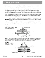
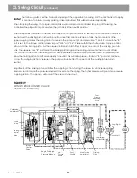
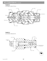
To simplify the swing control operation, right swing fluid path will be explained. Left swing will be similar in operation.
Note!
The right hand joystick controls the swing action on XL series machines. The joystick is connected directly to the torque
control valve.
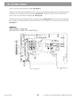
See Figure 38
When swinging, pilot fluid enters the torque control valve at port Y1. A shuttle valve isolates the 2 Y ports, tells the
control valve that swing right has been selected. This directs pilot circuit fluid to the maximum torque relief valve.
Internal drillings route pilot fluid to the right hand end cap of the torque control piston, and to the left hand end cap
of the stroking control piston in the brake valve.
As pilot pressure rises in the torque control valve, it shifts the control piston against the spring in the left hand end
cap. While the control piston shifts, it meters fluid from the X3 port of the stroking piston to tank. The brake valve
control piston shifts to the right, and meters charge circuit fluid into the stroking piston via port X4 .
With the pressure rise on one side of the stroking piston, it shifts the swashplate to give pump output from port A to
the swing motor. As pressure rises at the A pan on the pump, a signal is sent to the torque control valve from the
MA port on the pump through port 15. This signal shifts a shuttle valve, and through internal drillings routes fluid
to the torque control piston and to the end of the braking piston.
At the braking piston, the high pressure fluid shifts it to the left, and closes off ports X3 from 14. High pressure
fluid at the torque control piston works with the spring in the left hand end cap to balance pilot pressure in the right
hand end cap (at a 14.5 to 1 ratio, 1450 PSI pump output pressure, will balance 100 PSI pilot pressure).
When balance is achieved between the high pressure and pilot pressure, the torque control piston shifts to the right
and blocks fluid from the stroking piston being vented to tank. At this point, pump output pressure (torque) is
balanced against pilot input pressure. The output pressure will remain constant until pilot pressure is altered.
When maximum pump output pressure setting is reached, the torque relief valve opens to limit pilot pressure. When
pilot pressure limit is reached, output pressure is limited to swing circuit pressure setting for your machine.
FIGURE 38
SWING TORQUE CONTROL VALVE
(HYDRAULIC FUNCTION)
XI. Swing Circuit
(continued)
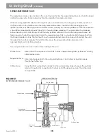
When in neutral, charge pressure is seen on both pump output ports and on both sides of
the stroking piston.
From
Pressure
Reducing
Valve
Cushioning
Adjustment
Brake Valve
Stroking
Control Piston
Swing Right
Swing Left
Right
Swing
From Swing
Suction Filter
Torque
Control
Piston
Begin Point/High
Pressure Balance
High
Pressure
SHuttle
Pilot
Shuttle
Max Torque
Adjustment
Stroking
Piston
35
Содержание XL4000
Страница 2: ......
Страница 73: ......
Страница 76: ... 5MP ...
Страница 145: ......
Страница 146: ......
Страница 151: ...From No 296020 2 97 4 FIGURE 4 FIGURE 5 FIGURE 3 IV Saving Charge and Pilot Pressure continued ...
Страница 160: ......
Страница 161: ......
Страница 162: ......
Страница 175: ......
Страница 176: ......
Страница 177: ......
Страница 178: ......
Страница 192: ......
Страница 193: ......
Страница 194: ......
Страница 207: ......
Страница 208: ......
Страница 210: ...500P ...
Страница 229: ......
Страница 230: ......
Страница 245: ......
Страница 246: ......
Страница 247: ......
Страница 248: ......
Страница 265: ......
Страница 266: ......
Страница 267: ......
Страница 268: ......
Страница 280: ......
Страница 281: ......
Страница 282: ......
Страница 297: ......
Страница 298: ......
Страница 299: ......
Страница 300: ......
Страница 301: ......
Страница 302: ......
Страница 303: ......
Страница 304: ......
Страница 305: ...GRADALL h y d r a u l i c e x c a v a t o r s XL 4000 5000 CENTER PIN REBUILD Form No 20026 Part No 2460 4164 ...


