X. Diverter Valve Testing
The diverter valve (P/N 8063-4028) is located in the front valve bank, next to the inlet section. The diverter valve is
connected to the rear valve bank inlet off the B port of the diverter valve.
The diverter valve performs a very important function in the hydraulic system by controlling the flow path of oil
from the two pump groups of the main pump. This valve allows excess oil in either valve bank to be mode
available to the other valve bank. It also gives priority of oil to the front valve bank (boom hoist and bucket) in
low flow, high pressure situations. The action of the diverter makes simultaneous function possible and prevents
any function from starving for oil in low flow, high pressure conditions.
To test for correct diverter function, use the boom and tool (bucket) circuit, engine at full RPM and the hydraulic oil
warmed to 120°F. Place the boom level, fully retracted with bucket fully bottomed against the stop. Return the
joysticks to neutral. Activate the boom joystick to extend the boom at full speed while moving the bucket joystick to
stall the bucket in the open position. While the boom is extending, release the bucket joystick allowing it to return
to neutral. If the diverter is working correctly, the boom will slow slightly, then speed up again when bucket is
released. If the diverter has failed, when the bucket comes to high pressure the boom will stop or very nearly stop.
Then when the high pressure (bucket) is released, after 1-2 seconds, the boom will start to extend again. If the
problem is the diverter sticking, this test may have to be repeated several times to confirm it.
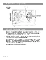
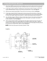
See Figure 10.
If gauges are being used during this test, you need a high pressure (10,000 PSI) gauge on the inlet test port (HP)
of each valve bank. Note the pressure when the boom starts running and watch it as the bucket is brought to high
pressure. The two gauges will rise, but will probably not be equal if the diverter is working correctly. If the diverter is
defective, the gauge on the front valve will rise to 4,300 PSI. The gauge on the rear test port will drop to 500-800
PSI and will not recover to the boom running pressure of 1,000-1,300 PSI until the boom starts to run again. When
pressure is let off the bucket, the front gauge will also drop.
See Figure 10.
If a diverter fails, it should be replaced. Always make sure the valve section shims (P/N 8093-4324) are in place at
the lie bolt holes when replacing a section. Use the parts book for correct tie bolt torque and torque sequence.
FIGURE 10
VALVE BANK
(TOP VIEW)
HP
HP
XL 4000/XL 5000 SERIES
HYDRAULIC PRESSURE SETTING MANUAL
(Supplemental Pressures)
Form No. 29705 3/99
15
Содержание XL4000
Страница 2: ......
Страница 73: ......
Страница 76: ... 5MP ...
Страница 145: ......
Страница 146: ......
Страница 151: ...From No 296020 2 97 4 FIGURE 4 FIGURE 5 FIGURE 3 IV Saving Charge and Pilot Pressure continued ...
Страница 160: ......
Страница 161: ......
Страница 162: ......
Страница 175: ......
Страница 176: ......
Страница 177: ......
Страница 178: ......
Страница 192: ......
Страница 193: ......
Страница 194: ......
Страница 207: ......
Страница 208: ......
Страница 210: ...500P ...
Страница 229: ......
Страница 230: ......
Страница 245: ......
Страница 246: ......
Страница 247: ......
Страница 248: ......
Страница 265: ......
Страница 266: ......
Страница 267: ......
Страница 268: ......
Страница 280: ......
Страница 281: ......
Страница 282: ......
Страница 297: ......
Страница 298: ......
Страница 299: ......
Страница 300: ......
Страница 301: ......
Страница 302: ......
Страница 303: ......
Страница 304: ......
Страница 305: ...GRADALL h y d r a u l i c e x c a v a t o r s XL 4000 5000 CENTER PIN REBUILD Form No 20026 Part No 2460 4164 ...


