Form No. 29703
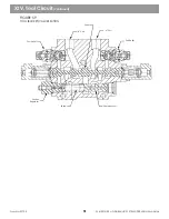
Load Sense
Cavity
Spool
Port Relief
B Part
A Part
Body
Port Relief
Tank Cavity
(2 Places)
Piloted
End Cap
Stroke Limiter (Fixed)
Retainer
Spring
Load Sense
Section
Regulator
Stroke Limiter
(Adjustable)
Load Sense
Port
Pump Supply
Cavity
Spring
Compensator
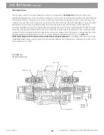
FIGURE 46
VALVE SECTION (TYPICAL)
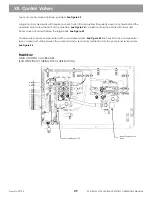
From the valve pressure cavity to the valve spool, the compensator works to allow a constant pressure drop.
See
Figure 44
It also functions as a load check until the pump flow overcomes the circuit pressure and prevents high
pressure in the valve bank from reaching the valve spool in neutral.
See Figure 45
It is designed to meter only
needed fluid to the valve spool while operating.
See Figure 46
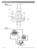
Primary shuttles read work port pressure and
signal the compensator. This signal also goes to secondary shuttles and to the pump load sense circuit.
See
Figure 47 The highest pressure work port signals the pump. The diverter valve has no shuttles.
Using a special compensator, the diverter valve sends excess fluid between valve banks. A shuttle in the diverter
compensator determines which is the higher pressure valve bank. The bucket and hoist valve bank has priority on
fluid from one pump section. In low flow conditions, the diverter forces fluid from one pump section into the
bucket and hoist bank. The diverter meters fluid from the two pump sections to match flow requirements in each
valve bank. It is possible, through the diverter, for both pump sections to be used to feed a single valve bank.
Clipper reliefs set at 5,100 PSI protect both valve bank inlets from pressure spikes.
See Figure 48
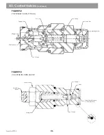
All valve section
work ports have port reliefs. These reliefs are internally piloted and will function as anti-cavitation checks when port
pressure drops below reservoir return pressure.
See Figure 49
Bucket, hoist and boom valves have pressure regulators in each compensator located below the rear end cap of
each valve.
See Figure 50
They are simple reliefs that open at a preset pressure to enable the compensator to
stop additional oil from getting to the valve spool (sufficient oil will be metered past the compensator to maintain
pressure in the function). This prevents oil from going over the reliefs and makes oil available to other functions
when a regulated function is stalled.
XII. Control Valves
(continued)
42
Содержание XL4000
Страница 2: ......
Страница 73: ......
Страница 76: ... 5MP ...
Страница 145: ......
Страница 146: ......
Страница 151: ...From No 296020 2 97 4 FIGURE 4 FIGURE 5 FIGURE 3 IV Saving Charge and Pilot Pressure continued ...
Страница 160: ......
Страница 161: ......
Страница 162: ......
Страница 175: ......
Страница 176: ......
Страница 177: ......
Страница 178: ......
Страница 192: ......
Страница 193: ......
Страница 194: ......
Страница 207: ......
Страница 208: ......
Страница 210: ...500P ...
Страница 229: ......
Страница 230: ......
Страница 245: ......
Страница 246: ......
Страница 247: ......
Страница 248: ......
Страница 265: ......
Страница 266: ......
Страница 267: ......
Страница 268: ......
Страница 280: ......
Страница 281: ......
Страница 282: ......
Страница 297: ......
Страница 298: ......
Страница 299: ......
Страница 300: ......
Страница 301: ......
Страница 302: ......
Страница 303: ......
Страница 304: ......
Страница 305: ...GRADALL h y d r a u l i c e x c a v a t o r s XL 4000 5000 CENTER PIN REBUILD Form No 20026 Part No 2460 4164 ...


