Form No. 29703
XL 4100/XL 5100 HYDRAULIC SYSTEM OPERATIONS MANUAL
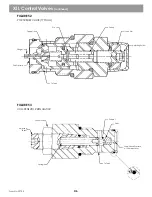
The torque control valve is mounted to the pump case. The torque control valve uses joystick output pressure to
control swing direction and pump output pressure (torque). A braking valve is attached to the torque control valve to
control hydraulic braking of the swing circuit when the joystick is centered.
The torque control valve has three adjustment screws. One limits torque output (maximum pressure) of the pump. The
other two screws control the begin point of the control (90 PSI to bring the pump on stroke) and the hydraulic
centering (high pressure balance) between the pump output ports. These would only be adjusted if a high pressure
imbalance existed between right (A) and left (B) port, or the pump came on stroke at a low/high pilot pressure.
The brake valve attached to the torque control valve has a single adjustment screw. Adjusting this screw will increase
or decrease the hydraulic braking while stopping. This valve only functions when the joystick is released and does
not affect the operation of the swing parking broke.
Note!
See Figure 35
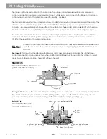
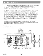
This view shows the pilot signal shuttle valve, and maximum torque control valve. This tells the torque
control valve direction of swing as selected by the operator, and limits maximum torque output by acting on the pilot
signal. Figure 36 shows pilot orifices. These limit oil flow to the relief.
See Figure 35
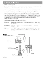
Shown are the torque control piston and high pressure shuttle valve. These two components perform
the functions of allowing the fluid in & out of the stroking piston. This provides the balance between pilot fluid
pressure and system pressure, and determining whether the machine is swinging or stopping.
XI. Swing Circuit
(continued)
The torque control valve and brake control valve work as a unit. They are considered two separate valves,
yet, both have to work together to give proper swing and swing stopping action. This is accomplished
as follows:
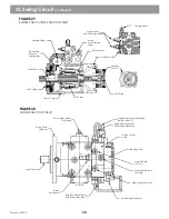
FIGURE 35
SWING TORQUE CONTROL VALVE:
(PILOT PRESSURE SECTION)
Maximum Torque
Adjustment
To Joystick
To Joystick
Pilot Pressure
Shuttle
Cushioning Valve
Assembly
FIGURE 36
SWING TORQUE VALVE:
(HIGH PRESSURE SECHON)
Test Port
High Pressure Shuttle
To
Pump
B Port
To Pump
A Port
Begin Point/High Pressure
Balance Adjustment
Torque Control Pistons
Begin Point/High Pressure
Balance Adjustment
33
Содержание XL4000
Страница 2: ......
Страница 73: ......
Страница 76: ... 5MP ...
Страница 145: ......
Страница 146: ......
Страница 151: ...From No 296020 2 97 4 FIGURE 4 FIGURE 5 FIGURE 3 IV Saving Charge and Pilot Pressure continued ...
Страница 160: ......
Страница 161: ......
Страница 162: ......
Страница 175: ......
Страница 176: ......
Страница 177: ......
Страница 178: ......
Страница 192: ......
Страница 193: ......
Страница 194: ......
Страница 207: ......
Страница 208: ......
Страница 210: ...500P ...
Страница 229: ......
Страница 230: ......
Страница 245: ......
Страница 246: ......
Страница 247: ......
Страница 248: ......
Страница 265: ......
Страница 266: ......
Страница 267: ......
Страница 268: ......
Страница 280: ......
Страница 281: ......
Страница 282: ......
Страница 297: ......
Страница 298: ......
Страница 299: ......
Страница 300: ......
Страница 301: ......
Страница 302: ......
Страница 303: ......
Страница 304: ......
Страница 305: ...GRADALL h y d r a u l i c e x c a v a t o r s XL 4000 5000 CENTER PIN REBUILD Form No 20026 Part No 2460 4164 ...


