Propel Circuit
The propel circuit of the XL 4100 AND XL 5100 REMOTE CONTROL EXCAVATORS converts hydraulic energy to
mechanical energy for total machine movement. This is accomplished as follows:
Filtered upperstructure hydraulic fluid is supplied to the system by the main and pilot pump circuits
Pilot circuit fluid is directed to main propel control valve forward or reverse end cap
Main propel control valve directs main pump fluid through the center pin to the propel (travel) motor
moving the machine
Machine brakes are released whenever the circuit is pressurized. They are spring-set, hydraulically released.
Motor case drain fluid is returned to the reservoir through the center pin
Return fluid passes through the center pin and control valves to the reservoir
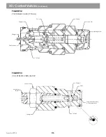
Propel fluid is routed through the center pin to the propel (travel) motor. On the XL 4100s, a Gertler-type motor is
used.
See Figure 64
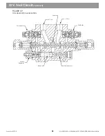
for XL 4100 Excavators. XL 5100 Excavators use a bent-axis piston motor. See Figure 31 The
motor drives through the truck transmission PTO for remote drive. The air cylinder of the PTO has detents on the
engage/disengage shift rail. After driving through the truck transmission, power is transmitted through the drive
shaft and axles to the rear wheels. On 6x6 units, the front wheels are also driven in remote if the transfer case is
engaged. Orifice check valves on the travel motor maintain back pressure in the motor while travelling to prevent
freewheeling down a grade. An air chamber on the truck chassis keeps the clutch disengaged whenever the
machine is in the remote control mode.
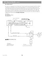
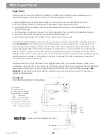
The travel pedal also controls the release of the digging brake system on the undercarriage. A shuttle valve is
connected to each pilot line to the Control valve. When the propel (travel) pedal is engaged, the pilot signal shifts
the propel and shuttle valve. Pilot fluid is directed through the center pin to the chassis interface valve.
See
Figure 68
This pilot signal hydraulically shifts the interface valve which signals the air portion of the valve to
release the digging brakes.
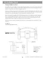
FIGURE 68
PILOT PROPEL CIRCUIT BLOCK DIAGRAM
Propel
Control
Valve
XVIII. Propel Circuit
Form No. 29703
60
Propel
Motor
Interface
Valve
Center
Pin
Tank
Main
Pump
Propel
Pedal
Pilot Pressure
Tank
Rev.
Fwd.
Rev.
P - Pilot Pressure
T - Return Fluid to Tank
A - Control Valve Port - Reverse
B - Control Valve Pon - forward
Check Valve
Orfice Check Valve
E - Center Pin Port - Case Drain
F - Center Pin Pon - Interface Value
1 & 2 - Center Pin Port To Propel Motor
Double Check Valve
Fwd.
Fwd.
Rev.
l
l
l
l
l
l
NOTE!
Hydraulic Fluid Path Simplified for Clarity
Содержание XL4000
Страница 2: ......
Страница 73: ......
Страница 76: ... 5MP ...
Страница 145: ......
Страница 146: ......
Страница 151: ...From No 296020 2 97 4 FIGURE 4 FIGURE 5 FIGURE 3 IV Saving Charge and Pilot Pressure continued ...
Страница 160: ......
Страница 161: ......
Страница 162: ......
Страница 175: ......
Страница 176: ......
Страница 177: ......
Страница 178: ......
Страница 192: ......
Страница 193: ......
Страница 194: ......
Страница 207: ......
Страница 208: ......
Страница 210: ...500P ...
Страница 229: ......
Страница 230: ......
Страница 245: ......
Страница 246: ......
Страница 247: ......
Страница 248: ......
Страница 265: ......
Страница 266: ......
Страница 267: ......
Страница 268: ......
Страница 280: ......
Страница 281: ......
Страница 282: ......
Страница 297: ......
Страница 298: ......
Страница 299: ......
Страница 300: ......
Страница 301: ......
Страница 302: ......
Страница 303: ......
Страница 304: ......
Страница 305: ...GRADALL h y d r a u l i c e x c a v a t o r s XL 4000 5000 CENTER PIN REBUILD Form No 20026 Part No 2460 4164 ...

