5
IV. Cylinders
There are seven hydraulic cylinders used on the GRADALL XL 4100 and XL 5100 HYDRAULIC REMOTE CONTROL
MACHINES. There is (1) Boom Cylinder (moves telescope boom in/out), (2) Hoist Cylinders (Pivots boom
up/down), (1) Tool Cylinder (Open & Closes Bucket). (1) Steer Cylinder (moves front wheels right or left), and (2)
Oscillation Lock Cylinders (Stabilizes front of machine when in digging mode.) If cylinder by pass or fluid leakage
is detected, contact GRADALL distributor for analysis and correction. Cylinder bypass is usually detected by
movement of the structure the cylinder is attached to whenever the control valve (Joystick setting) is in Neutral.
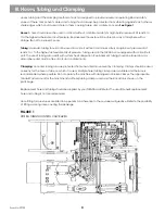
Boom Cylinder:
Function: Extends and retracts the telescope boom.
Location: Inside main and telescope boom.
Receives fluid through a hydraulic gland fastened to the rear of the cylinder rod.
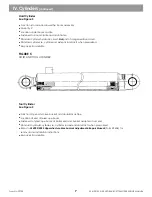
The main components shown on
Figure 2
are:
Cylinder Barrel
Housing for cylinder rod and piston. Receptacle for hydraulic fluid. Extends and retracts when pressurized.
Cylinder Barrel Ball Joint
Fastens to the telescope boom. Allows for cylinder angular movement as the boom extends and retracts.
Cylinder Rod
Component to which the piston is attached. Fastened to the boom cradle rear plate at the rod bearing retainer.
The hollow rod is equipped with an internal hydraulic tube that carries fluid to the barrel end of the cylinder.
Internal Cylinder Rod
Function is to carry hydraulic fluid to the barrel end of the cylinder. Location is inside of the cylinder rod.
Cylinder Gland
Function to deliver fluid to selected port in the cylinder. Equipped with seals that allow rotation & prevents fluid
leakage. Allows for boom tilt.
Rod Bearing
Location: back of the cradle in boom cylinder retainer. Function: Provide structural attachment of the boom cylinder
rod to the boom. Allows the boom cylinder rod to rotate and flex (during boom movement) without binding.
Locknut
Function: to secure boom cylinder in the boom. Location: at back of boom cylinder retainer plate.
Refer to
XL 4000/5000 Upperstructure Mechanical Adjustment & Repair Manual
(Form 29604) for
bearing and locknut removal and installation instructions.
Extend is part of a regenerative circuit. Fluid from rod side joins fluid from the pump to fill the barrel side
whenever the telescope boom extends. Equal pressure is then available to both sides of cylinder piston. Larger
barrel area forces boom to move out.
See Figure 3 and Figure 65
Retract circuit - Has porting designed into the cylinder rod O.D. Fluid passes through these ports, supplying the
cylinder rod side area inside the barrel, retracting boom. This side of the circuit is not nogenerative.
See Figures 4 and Figure 64
Re-pack kits available.
Refer to
XL 4000/5000 Upperstructure Mechanical Adjustment & Repair Manual
(Form 29604) for
removal & installation instructions.
l
l
l
l
l
l
l
l
XL 4100/XL 5100 HYDRAULIC SYTEM OPERATIONS MANUAL
Form No. 29703
Содержание XL4000
Страница 2: ......
Страница 73: ......
Страница 76: ... 5MP ...
Страница 145: ......
Страница 146: ......
Страница 151: ...From No 296020 2 97 4 FIGURE 4 FIGURE 5 FIGURE 3 IV Saving Charge and Pilot Pressure continued ...
Страница 160: ......
Страница 161: ......
Страница 162: ......
Страница 175: ......
Страница 176: ......
Страница 177: ......
Страница 178: ......
Страница 192: ......
Страница 193: ......
Страница 194: ......
Страница 207: ......
Страница 208: ......
Страница 210: ...500P ...
Страница 229: ......
Страница 230: ......
Страница 245: ......
Страница 246: ......
Страница 247: ......
Страница 248: ......
Страница 265: ......
Страница 266: ......
Страница 267: ......
Страница 268: ......
Страница 280: ......
Страница 281: ......
Страница 282: ......
Страница 297: ......
Страница 298: ......
Страница 299: ......
Страница 300: ......
Страница 301: ......
Страница 302: ......
Страница 303: ......
Страница 304: ......
Страница 305: ...GRADALL h y d r a u l i c e x c a v a t o r s XL 4000 5000 CENTER PIN REBUILD Form No 20026 Part No 2460 4164 ...


