XL 4100/5100 HYrDARAULIC SYSTEM OPERATIONS MANUAL
Form No. 29703
Standard Steering Circuit
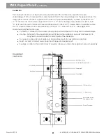
When the machine is in the normal travel mode, it steers from the truck cab. There is a conventional power
steering circuit on the chassis.
DO NOT RUN the upperstructure engine when driving the machine from the carrier. Tank fluid pressure
could react on the remote steering cylinder making steering more difficult.
Hydraulic Remote Steering Circuit
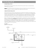
When the machine is in the remote mode it steers from the upperstructure cab.Whenever the steering pedal is
depressed in either direction, pilot fluid is directed through Ports A & C in the center pin to the steering valve
located on the front right frame rail of the chassis. This fluid shifts the spool directing main fluid to the steering
cylinder forcing a right or left turn. Axle stops and an adjustable rod end prevent the cylinder from bottoming
mechanically. The steering cylinder is connected to the right side of the chassis frame and the steering axle.
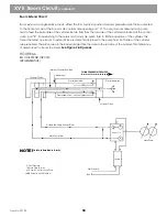
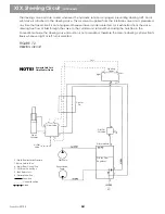
Fluid for the steering cylinder is supplied by the Recirculating Pump. Fluid from the pump flows to the Priority Flow
Regulator in the Pilot Manifold.
See Figure 71
The priority flow regulator diverts a portion of the 14 GPM from the
pump delivering it to the steering valve through the center pin. Port 4. The maximum flow to the steering valve is 4
GPM. The steering circuit is protected by a 2100 PSI relief valve in the pilot manifold. The steering cylinder is
protected by a 2000 PSI port relief valve in the steering valve. Return fluid from the steering valve is returned to the
reservoir through Pon 3 in the center pin.
FIGURE 71
PRIORITY FLOW REGULATOR
XIX. Steering Circuit
Note!
63
To Pressure
Reducing Valve
To Pilot Cut-Off
Valve
From Pilot Pump
To Steering
Valve
From Recirculation
Pump
Priority Flow
Regulator
(In Pilot Manifold)
From Steering
Valve
To Tank
4.0 GPM
6.6 GPM
14 GPM
480
PSI
2,100
PSI
Содержание XL4000
Страница 2: ......
Страница 73: ......
Страница 76: ... 5MP ...
Страница 145: ......
Страница 146: ......
Страница 151: ...From No 296020 2 97 4 FIGURE 4 FIGURE 5 FIGURE 3 IV Saving Charge and Pilot Pressure continued ...
Страница 160: ......
Страница 161: ......
Страница 162: ......
Страница 175: ......
Страница 176: ......
Страница 177: ......
Страница 178: ......
Страница 192: ......
Страница 193: ......
Страница 194: ......
Страница 207: ......
Страница 208: ......
Страница 210: ...500P ...
Страница 229: ......
Страница 230: ......
Страница 245: ......
Страница 246: ......
Страница 247: ......
Страница 248: ......
Страница 265: ......
Страница 266: ......
Страница 267: ......
Страница 268: ......
Страница 280: ......
Страница 281: ......
Страница 282: ......
Страница 297: ......
Страница 298: ......
Страница 299: ......
Страница 300: ......
Страница 301: ......
Страница 302: ......
Страница 303: ......
Страница 304: ......
Страница 305: ...GRADALL h y d r a u l i c e x c a v a t o r s XL 4000 5000 CENTER PIN REBUILD Form No 20026 Part No 2460 4164 ...


