XIX. Crawler Motor and Final Drive
62
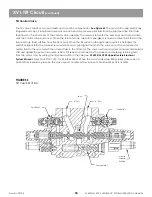
The hydraulic crawler motor and final drive are specifically designed to be an excavator drive assembly.
See Figure
69
This assembly consists of a spring-applied parking brake, a double counterbalance valve, a two-speed valve,
crossover relief valves, an inline piston motor and a three-stage planetary reduction unit.
The crawler motor converts hydraulic power into mechanical power. It is equipped with a planetary reduction box that
reduces motor speed and increases the motor output torque thereby providing power to drive the crawler tracks.
The following are the major features of the final drive assembly. Refer to the appropriate section for a detailed
description of each major component.
Piston motor and brake assembly
The parking brake is built into the motor housing which consists of a spring set and hydraulic release brake. The
parking brake provides a mechanical lock for the final drive when the drive is not actuated. The piston motor is
a compact, inline position motor that fits within the spindle of the final drive. The piston motor is designed to give
high volumetric efficiency along with high starting torque. The end cover of the motor incorporates a double
counterbalance valve.
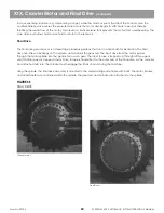
Final Drive Assembly
The final drive assembly is a three-stage planetary reducer that multiplies motor output torque to a sufficient level
that will drive the tracks. The spindle of the final drive provides mounting for the piston motor, brake and side frame.
The sprocket attaches to the final drive to provide tractive effort to the tracks.
Motor Assembly
The motor assembly is in the back side of the final drive spindle, when the final drive is mounted on the machine.
The motor assembly can be removed from the final drive separately. The end cover of the motor provides for all
motor ports, a counterbalance valve and a two-speed valve. The valve to release the final drive parking broke is part
of the counterbalance valve. To protect the motor against high pressure spikes, the end cover also contains two
shockless reliefs. There is a port plate between the motor rotary group and end cover. Ports in the plate allow oil to
flow in and out of the motor. These ports also connect the ports P1 and P2 in the motor end cover.
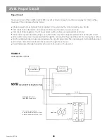
The two-position inline piston motor uses a swash plate to change the motor swivel angle. This swash plate is
controlled by two stroking pistons. These stroking pistons are controlled by a two-speed valve in the motor end cover.
The two-speed valve is controlled by a pilot signal from the upperstructure. The swash plate is spring-loaded to the
low speed (high torque) position. When the two-speed valve is shifted, circuit fluid is directed to the stroking pistons,
shifting the swash plate to the high speed (low torque) position.
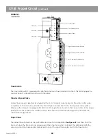
The counterbalance valve hydraulically locks the motor when the circuit is not actuated. When the circuit is actuated,
the counterbalance valve prevents the motor from overrunning while descending a grade. When the control valve is
shifted, circuit fluid is routed to the counterbalance valve which wont shift until fluid from the control valve over-
comes fluid trapped between the counterbalance valve and the motor. As the counterbalance valve shifts, a signal of
fluid to the brake piston releases the drive parking brake. This brake remains released until the counterbalance valve
resets. If the machine is being turned with only one track, the brake is only released in the final drive being powered
Form No. 29704
Содержание XL4000
Страница 2: ......
Страница 73: ......
Страница 76: ... 5MP ...
Страница 145: ......
Страница 146: ......
Страница 151: ...From No 296020 2 97 4 FIGURE 4 FIGURE 5 FIGURE 3 IV Saving Charge and Pilot Pressure continued ...
Страница 160: ......
Страница 161: ......
Страница 162: ......
Страница 175: ......
Страница 176: ......
Страница 177: ......
Страница 178: ......
Страница 192: ......
Страница 193: ......
Страница 194: ......
Страница 207: ......
Страница 208: ......
Страница 210: ...500P ...
Страница 229: ......
Страница 230: ......
Страница 245: ......
Страница 246: ......
Страница 247: ......
Страница 248: ......
Страница 265: ......
Страница 266: ......
Страница 267: ......
Страница 268: ......
Страница 280: ......
Страница 281: ......
Страница 282: ......
Страница 297: ......
Страница 298: ......
Страница 299: ......
Страница 300: ......
Страница 301: ......
Страница 302: ......
Страница 303: ......
Страница 304: ......
Страница 305: ...GRADALL h y d r a u l i c e x c a v a t o r s XL 4000 5000 CENTER PIN REBUILD Form No 20026 Part No 2460 4164 ...


