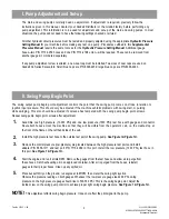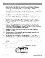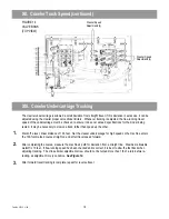
V. Pump Horsepower Adjustment
The following procedure is for testing and setting the pump horsepower adjustment. The pump horsepower
affects the point the pump de-strokes to keep from drawing more horsepower than con be delivered. This test
con be affected by the weight of material in the bucket. It is recommended that the biggest bucket available for
the machine, heaped with dirt, be used to set pump horsepower. If the pump horsepower adjustment is altered,
a new seal cop must be installed on the pump horsepower adjustment screw.
All pressures must be correct before testing pump horsepower. If any pressures ore incorrect, the
pump horsepower setting will be affected.
Use the tachometer on the monitor system for this procedure. The largest bucket available must be heaped with
dirt. Then with the machine in a clear area, place the bucket on the ground. On XL 4100 and XL 5100 machines,
make sure that the boom will not come in contact with the carrier cab while swinging. When testing the pump
horsepower of these models, it is recommended that the bucket be placed on the ground, on the left-hand side
of the machine. The machine should be swung to the left. Do not stall any function while performing this test.
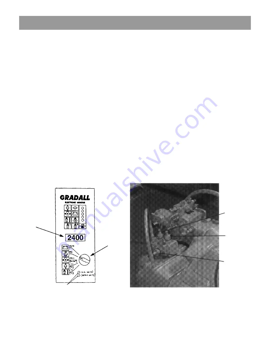
See Figure 5.
With the full bucket on the ground and the engine at full RPM, use the controls to hoist-up, boom-out and
swing left at the some time. Observe engine RPM. It should not drop below 1,900 RPM. If adjustment is
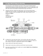
required, use the horsepower adjustment screw (front adjustment screw on front of pump controls on main
pump). Turning the screw clockwise decreases RPM drawdown; turning the screw counter-clockwise increases RPM
drawdown.
See Figure 6.
FIGURE 5
ELECTRONIC MONITOR PANEL
NOTE!
1.
2.
FIGURE 6
PUMP CONTROLS
Pump Cut-off
Adjustment Screw
Pump Horsepower
Adjustment Screw
Pump Standby
Adjustment Screw
Use display to
check RPM drop
GREEN LEDS
Set switch
to RPM
Form No. 29705 3/99
10
Содержание XL4000
Страница 2: ......
Страница 73: ......
Страница 76: ... 5MP ...
Страница 145: ......
Страница 146: ......
Страница 151: ...From No 296020 2 97 4 FIGURE 4 FIGURE 5 FIGURE 3 IV Saving Charge and Pilot Pressure continued ...
Страница 160: ......
Страница 161: ......
Страница 162: ......
Страница 175: ......
Страница 176: ......
Страница 177: ......
Страница 178: ......
Страница 192: ......
Страница 193: ......
Страница 194: ......
Страница 207: ......
Страница 208: ......
Страница 210: ...500P ...
Страница 229: ......
Страница 230: ......
Страница 245: ......
Страница 246: ......
Страница 247: ......
Страница 248: ......
Страница 265: ......
Страница 266: ......
Страница 267: ......
Страница 268: ......
Страница 280: ......
Страница 281: ......
Страница 282: ......
Страница 297: ......
Страница 298: ......
Страница 299: ......
Страница 300: ......
Страница 301: ......
Страница 302: ......
Страница 303: ......
Страница 304: ......
Страница 305: ...GRADALL h y d r a u l i c e x c a v a t o r s XL 4000 5000 CENTER PIN REBUILD Form No 20026 Part No 2460 4164 ...


