


ADP200 • Quick installation guide - Specifications and connection
89
A.3 Encoders and encoder expansion cards
A.3.1 Encoders
Encoders provide motor speed and position feedback.
The regulation algorithms in the ADP200 drive are capable of controlling permanent magnet synchronous (brushless)
motors. With brushless motors the regulation algorithm needs an encoder that also allows the absolute motor position
to be verified.
The standard ADP200 drive supports resolver encoders managed via the standard encoder card. The type of encoder
that is connected must be selected via software: PAR 2132 Encoder
1
mode (menu 15 - ENCODER CONFIG).
Selecting the transformation ratio via jumper.
The drive ADP200 supports different types of encoders, each managed by a specific expansion card. The card is
automatically recognised at startup.
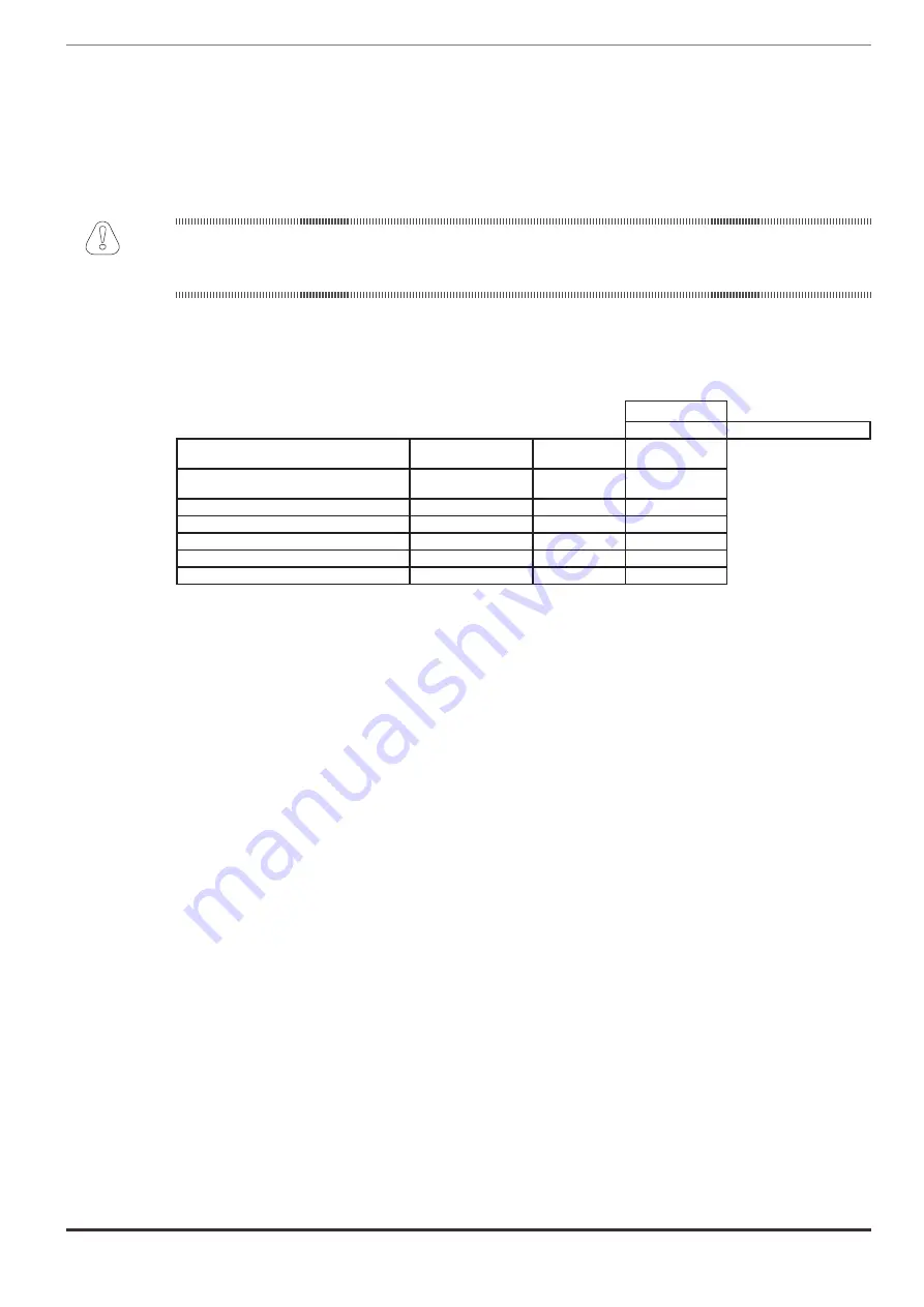
Possible configurations are summarised in the table:
Brushless
Flux Vector CL
PAR 552 – Regulation mode
Encoder type
Card
PAR 532,
Slot2 card type
Resolver
EXP-RES-I1-ADP
(EXP-RES-I1R1-ADP)
Enc 6
Default
Incremental Digital
EXP-DE-I1R1F2-ADL
Enc 1
Possible
Incremental sinusoidal
EXP-SE-I1R1F2-ADL
Enc 2
Possible
Incremental sinu absolute SinCos
EXP-SESC-I1R1F2-ADL
Enc 3
Recommended
Incremental sinu Absolute Endat/SSI
EXP-EN/SSI-I1R1F2-ADL
Enc 4
Recommended
Incremental sinu Hiperface absolute
EXP-HIP-I1R1F2-ADL
Enc 5
Recommended
Encoders must be fitted to the motor shaft using anti-backlash couplings.
For electrical connections always use good quality cables with shielded twisted pairs, according to the procedures and
specifications described in the following paragraphs.
The configuration parameters for each encoder can be found in the ENCODER CONFIG.
In the event of an encoder malfunction the drive generates the
Speed fbk loss
alarm and the cause of the malfunction
is shown in parameter 2172
SpdFbkLoss code
.
If the encoder is not used by the regulation algorithm the drive still manages the encoder position reading but does not
generate an alarm in case of malfunctioning.
Attention