5-7
5-2 NP1F-MP1 I/O Area
)
t
e
s
e
r
r
e
t
n
u
o
c
e
u
l
a
v
t
n
e
r
r
u
c
o
t
e
s
n
o
p
s
e
R
:
e
m
a
n
l
a
n
g
i
S
(
4
t
i
B
<Description>
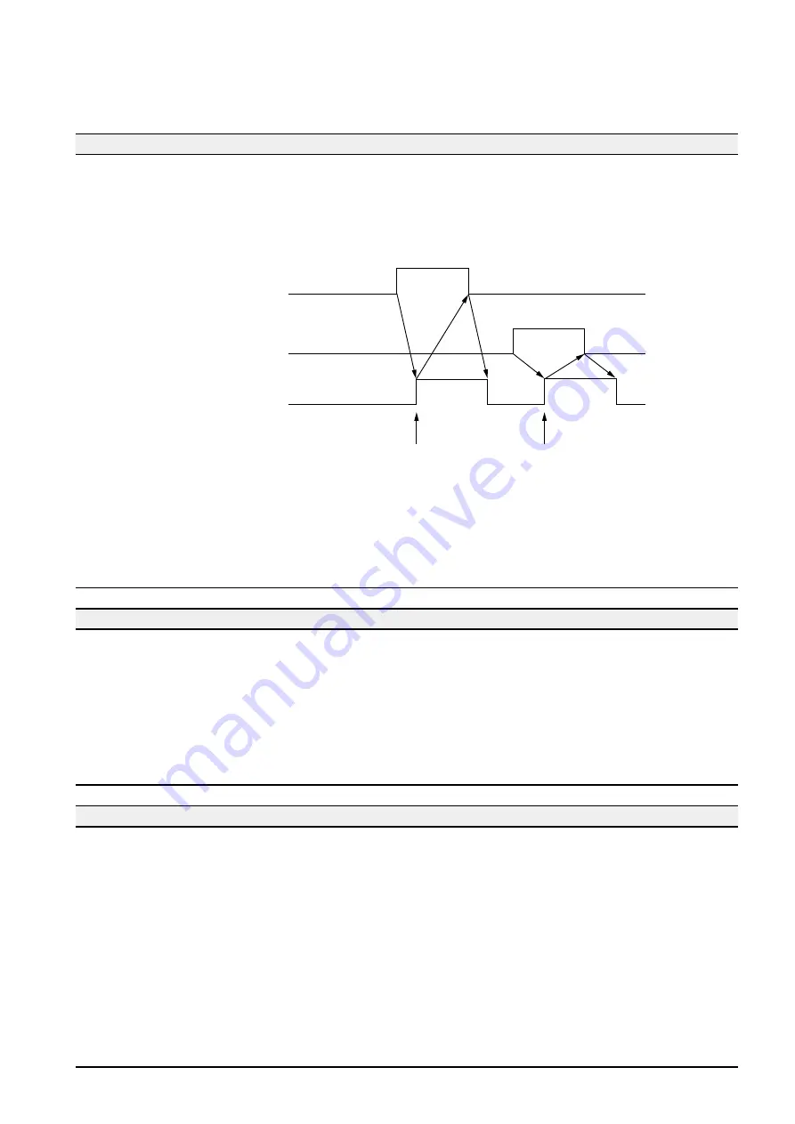
• This is a response signal to the current value counter reset command or command pulse register reset command
in the pulse generation mode.
This signal becomes “1” while the current value counter reset command or command pulse register reset
command is “1.”
Current value counter reset
command (PC == > MP1)
Command pulse register reset
command (PC == > MP1)
Response to current counter
reset (PC <== MP1)
“1”
“1”
“1”
“1”
Current value counter
is reset.
FIFO buffer for the command
pulse register is reset.
• In the position command mode, when the command pulse register reset command is issued, the start signal for
module internal processing is turned OFF, and pulse output is stopped. Even in this case, response to reset
command becomes “1,” corresponding to the command pulse reset command.
)
g
n
i
g
n
a
h
c
d
e
e
p
S
:
e
m
a
n
l
a
n
g
i
S
(
5
t
i
B
<Description>
• This is a response signal to the speed change command in the pulse generation mode.
While this signal is “1,” the values stored in the set value data area are continuously written in the “target frequency
register.”
Frequency (speed) data can be changed from the CPU module.
(For details, refer to the paragraph for speed change command.)
• In the position command mode, the speed change command signal continues to be “0.”
)
t
c
e
t
e
d
l
a
n
g
i
s
Z
-
e
s
a
h
P
:
e
m
a
n
l
a
n
g
i
S
(
6
t
i
B
<Description>
• In the pulse generation mode or position command mode, this signal becomes “1” when an effective phase-Z
signal is detected after the phase-Z signal detect command has become “1.”
While this signal is “1,” the deviation amount data when phase-Z was detected or the lower word of the current
value counter when phase-Z was detected is output in the current value data area (address No. 3). (Output data is
selected by Latch Data Output Select.)
When the phase-Z signal detect command has become “0,” this signal becomes “0,” and the current value data
area (address No. 3) returns to current value counter upper word output mode.
(For details, refer to the paragraph for phase-Z signal detect command.)
Содержание micrex-sx NP1F-MP1
Страница 1: ...FEH214a series USER S MANUAL PULSE TRAIN POSITIONING CONTROL COMBINED MODULE...
Страница 28: ...3 10 3 4 Dimensions 3 4 1 NP1F MP1 for 1 axis 3 4 2 NP1F MP2 for 2 axes 90 46 5 75 35 105...
Страница 29: ...3 11 3 4 Dimensions 3 4 3 NP2F LEV Signal converter 95 47 2 10 29 8 39 8 85 95 40 36 6...
Страница 223: ...Section 8 Troubleshooting Page 8 1 LED Indication 8 1 8 2 Error Indication 8 2...


