


5-17
5-2 NP1F-MP1 I/O Area
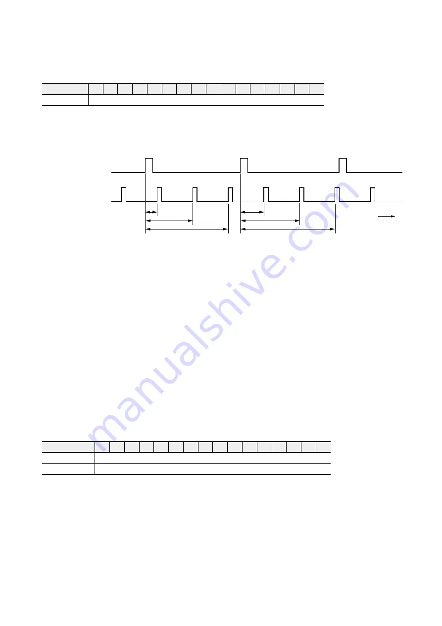
(6) Module detection time (Address No. 9)
.
o
N
s
s
e
r
d
d
A
5
1
4
1
3
1
2
1
1
1
0
1
9
8
7
6
5
4
3
2
1
0
9
e
m
i
t
n
o
i
t
c
e
t
e
d
e
l
u
d
o
M
• Module detection time data output area
Module output time is the time measured by in
µ
s since transmission end interrupt was made on the SX bus until
periodic processing is started on the module.
SX bus
send end
Module
detection time
Time
Module
periodic timer
On the module side, the above timer value (module detection time) is also updated when the output data to the SX
bus (CPU module input signal) is updated.
• From this data, the external pulse input frequency can be calculated.
f: Frequency Hz
T: Takt time
µ
s
T
n-1
: Previous module detection time
µ
s
t
n
: Current module detection time
µ
s
P
n-1
: Previous count value pulse
P
n
: Current count value pulse
f = (P
n
- P
n-1
) / (T - t
n-1
+ T
n
) x 1000 x 1000
Precautions:
• The time until module detection time overflows is 65.5ms.
When an overflow has occurred, this value returns to “0,” and the timer count is continued (ring operation).
Feedback pulse frequency and command pulse frequency are also calculated according to the above formula.
• This data is used, for example, to calculate the expected position of the spindle after the unit time has elapsed in
synchronous operation.
• Because the updating interval of this positioning module is 800
µ
s (asynchronous with the tact time of the system),
maximum
±
800
µ
s of deviation may occur.
(7) Current external pulse data (Address No. 6: lower word; address No. 7: upper word)
.
o
N
s
s
e
r
d
d
A
5
1
4
1
3
1
2
1
1
1
0
1
9
8
7
6
5
4
3
2
1
0
6
)
d
r
o
w
r
e
w
o
l
(
d
a
e
r
a
t
a
d
e
s
l
u
p
l
a
n
r
e
t
x
e
t
n
e
r
r
u
C
7
)
d
r
o
w
r
e
p
p
u
(
d
a
e
r
a
t
a
d
e
s
l
u
p
l
a
n
r
e
t
x
e
t
n
e
r
r
u
C
Precaution:
• The upper word is the same as that of the current value. When an interrupt is detected, the lower at the time of
detection is output.
Содержание micrex-sx NP1F-MP1
Страница 1: ...FEH214a series USER S MANUAL PULSE TRAIN POSITIONING CONTROL COMBINED MODULE...
Страница 28: ...3 10 3 4 Dimensions 3 4 1 NP1F MP1 for 1 axis 3 4 2 NP1F MP2 for 2 axes 90 46 5 75 35 105...
Страница 29: ...3 11 3 4 Dimensions 3 4 3 NP2F LEV Signal converter 95 47 2 10 29 8 39 8 85 95 40 36 6...
Страница 223: ...Section 8 Troubleshooting Page 8 1 LED Indication 8 1 8 2 Error Indication 8 2...