7-33
7-4 Functions of the Position Command Mode
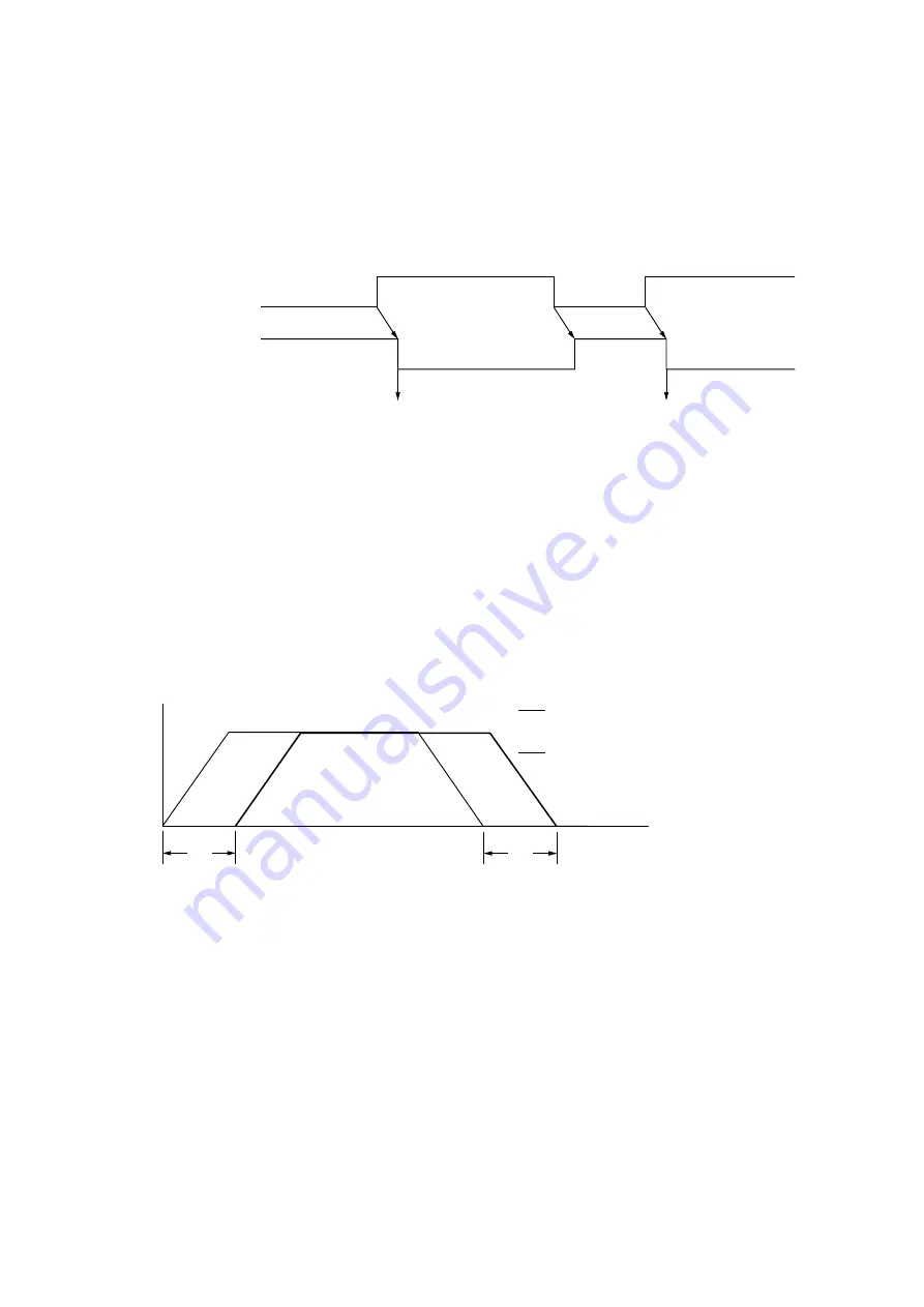
7-4-2 Operation at the rising edge of start signal
• In the position command mode, while the start command is “1,” the increment is calculated from the position data
sent from the CPU module.
• For the calculation of the increment, it is necessary to continuously back up the previous setting. Therefore, at the
rising edge at which the start command signal changes from “0” to “1,” the set value for position data is fetched as
the previous data (presetting of previous data). Then the calculation of the increment is started.
Start command
(PC == > MP1/MP2)
“1”
“1”
Positioning end
(PC <== MP1/MP2)
Presetting of previous data
Presetting of previous data
“0”
“0”
7-4-3 Operation when start command is “ON”
• In the position command mode, positioning is executed using delay time.
• In the position command mode, the number of pulses which are to be output for the unit-time period as well as the
frequency are automatically calculated and set from the position data sent from the SX bus. ( For how to calculate
the value to be set in the target frequency register, refer to page 7-33.)
(1) Set values for each register (values automatically set in the module)
In the position command mode, the following values are automatically set:
1) Frequency register: fixed to 16-bit length
2) Maximum frequency: 1MHz (fixed)
(2) Processing of delay time in the position command mode
This module makes the command to move to the target position after the specified delay time elapses, making the
transmission signal from the SX bus the reference. As a result, the relationship between the command sent from
this module and that from the SX bus becomes as shown below:
Speed
Command from SX bus
Output of the module
T
T
Time
T: Delay time
Содержание micrex-sx NP1F-MP1
Страница 1: ...FEH214a series USER S MANUAL PULSE TRAIN POSITIONING CONTROL COMBINED MODULE...
Страница 28: ...3 10 3 4 Dimensions 3 4 1 NP1F MP1 for 1 axis 3 4 2 NP1F MP2 for 2 axes 90 46 5 75 35 105...
Страница 29: ...3 11 3 4 Dimensions 3 4 3 NP2F LEV Signal converter 95 47 2 10 29 8 39 8 85 95 40 36 6...
Страница 223: ...Section 8 Troubleshooting Page 8 1 LED Indication 8 1 8 2 Error Indication 8 2...


