21 REMOTE CONTROLLER (REMC)
286
EPSON
S1C17001 TECHNICAL MANUAL
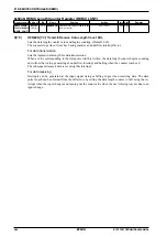
0x5347: REMC Interrupt Flag Register (REMC_IFLG)
Register name Address
Bit
Name
Function
Setting
Init. R/W
Remarks
REMC Interrupt
Flag Register
(REMC_IFLG)
0x5347
(8 bits)
D7–3
–
reserved
–
–
–
0 when being read.
D2
REMFIF
Falling edge interrupt flag
1 Cause of
interrupt
occurred
0 Cause of
interrupt not
occurred
0
R/W Reset by writing 1.
D1
REMRIF
Rising edge interrupt flag
0
R/W
D0
REMUIF
Underflow interrupt flag
0
R/W
This register indicates the occurrence status of interrupt factors arising from data length counter underflow, input
signal rising edge, or input signal falling edge. When an REMC interrupt occurs, the interrupt flag in this register
should be inspected to identify the interrupt factor.
Setting the corresponding interrupt enable bit to 1 sets the interrupt flag to 1 when a data length counter underflow,
input signal rising edge, or input signal falling edge occurs. The REMC outputs an interrupt request signal to the
ITC at the same time, which sets the REMC interrupt flag to 1 within the ITC and generates an interrupt if the ITC
and S1C17 core interrupt conditions are met.
Note: To prevent generating unnecessary interrupts, reset the interrupt flag before permitting inter-
rupts by the interrupt enable bit.
D2
REMFIF: Falling Edge Interrupt Flag
Interrupt flag indicating the falling edge interrupt occurrence status.
1(R):
Interrupt factor present
0(R):
No interrupt factor (default)
1(W):
Reset
flag
0(W):
Disabled
Setting REMFIE (D2/REMC_IMSK register) to 1 sets SIF1 to 1 at the input signal falling edge.
D1
REMRIF: Rising Edge Interrupt Flag
Interrupt flag indicating the rising edge interrupt factor occurrence status.
1(R):
Interrupt factor present
0(R):
No interrupt factor (default)
1(W):
Reset
flag
0(W):
Disabled
Setting REMRIF (D1/REMC_IMSK register) to 1 sets REMRIE to 1 at the input signal falling edge.
D0
REMUIF: Underflow Interrupt Flag
Interrupt flag indicating the underflow interrupt factor occurrence status.
1(R):
Interrupt factor present
0(R):
No interrupt factor (default)
1(W):
Reset
flag
0(W):
Disabled
Setting REMUIE (D1/REMC_IMSK register) to 1 sets REMUIF to 1 when a data length counter under-
flow occurs.
Содержание S1C17001
Страница 1: ...Technical Manual S1C17001 CMOS 16 BIT SINGLE CHIP MICROCONTROLLER ...
Страница 31: ...3 MEMORY MAP AND BUS CONTROL 22 EPSON S1C17001 TECHNICAL MANUAL This page intentionally left blank ...
Страница 33: ...4 POWER SUPPLY VOLTAGE 24 EPSON S1C17001 TECHNICAL MANUAL This page intentionally left blank ...
Страница 63: ...6 INITERRUPT CONTROLLER 54 EPSON S1C17001 TECHNICAL MANUAL This page intentionally left blank ...
Страница 87: ...8 CLOCK GENERATOR CLG 78 EPSON S1C17001 TECHNICAL MANUAL This page intentionally left blank ...
Страница 91: ...9 PRESCALER PSC 82 EPSON S1C17001 TECHNICAL MANUAL This page intentionally left blank ...
Страница 133: ...11 16 BIT TIMER T16 124 EPSON S1C17001 TECHNICAL MANUAL This page intentionally left blank ...
Страница 185: ...14 8 BIT OSC1 TIMER T8OSC1 176 EPSON S1C17001 TECHNICAL MANUAL This page intentionally left blank ...
Страница 211: ...16 STOPWATCH TIMER SWT 202 EPSON S1C17001 TECHNICAL MANUAL This page intentionally left blank ...
Страница 219: ...17 WATCHDOG TIMER WDT 210 EPSON S1C17001 TECHNICAL MANUAL This page intentionally left blank ...
Страница 241: ...18 UART 232 EPSON S1C17001 TECHNICAL MANUAL This page intentionally left blank ...
Страница 277: ...20 I2 C 268 EPSON S1C17001 TECHNICAL MANUAL This page intentionally left blank ...
Страница 297: ...21 REMOTE CONTROLLER REMC 288 EPSON S1C17001 TECHNICAL MANUAL This page intentionally left blank ...
Страница 303: ...22 ON CHIP DEBUGGER DBG 294 EPSON S1C17001 TECHNICAL MANUAL This page intentionally left blank ...
Страница 313: ...25 PACKAGE 304 EPSON S1C17001 TECHNICAL MANUAL This page intentionally left blank ...

