19 SPI
S1C17001 TECHNICAL MANUAL
EPSON
237
19.5 Data Transfer Control
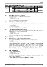
Make the following settings before starting data transfers.
(1) Set the 16-bit timer Ch.1 to output the SPI clock. (See Section 11.)
(2) Select Master mode or Slave mode. (See Section 19.4.)
(3) Set clock conditions. (See Section 19.4.)
(4) Set the interrupt conditions to use SPI interrupts. (See Section 19.6.)
Note: Make sure the SPI is halted (when SPEN/SPI_CTL register = 0) before changing the above set-
tings.
∗
SPEN
: SPI Enable Bit in the SPI Control (SPI_CTL) Register (D0/0x4326)
Permitting data transfers
Set the SPEN bit (D0/SPI_CTL register) to 1 to permit SPI operations. This enables SPI transfers and permits
clock input/output.
Note: Do not set SPEN to 0 when the SPI module is transferring data.
Data transfer control
To start data transmission, write the transmission data to the SPI_TXD register (0x4322).
∗
SPI_TXD
: SPI Transmit Data Register (0x4322)
The data is written to the transmit data buffer, and the SPI module begins sending data. The buffer data is sent
to the transmit shift register. In Master mode, the module starts clock output from the SPICLK pin. In Slave
mode, the module awaits clock input from the SPICLK pin. The data in the shift register is shifted in sequence
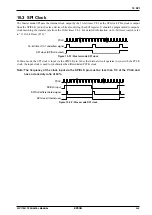
at the clock rising or falling edge, as determined by CPHA (D3/SPI_CTL register) and CPOL (D2/SPI_CTL
register) (see Figure 19.4.1) and sent from the SDO pin with MSB leading.
∗
CPHA
: Clock Phase Select Bit in the SPI Control (SPI_CTL) Register (D3/0x4326)
∗
CPOL
: Clock Polarity Select Bit in the SPI Control (SPI_CTL) Register (D2/0x4326)
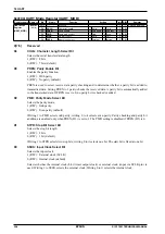
The SPI module includes the SPTBE (D0/SPI_ST register) and SPBSY (D2/SPI_ST register) status flags for
transfer control.
∗
SPTBE
: Transmit Data Buffer Empty Flag in the SPI Status (SPI_ST) Register (D0/0x4320)
∗
SPBSY
: Transfer Busy Flag in the SPI Status (SPI_ST) Register (D2/0x4320)
The SPTBE flag indicates the transmit data buffer status. This flag switches to 0 when the application program
writes data to the SPI_TXD register (transmit data buffer) and reverts to 1 when the buffer data is sent to the
transmit shift register. Interrupts can be generated when this flag is 1 (see Section 19.6). Subsequent data is sent
after confirming that the transmit data buffer is empty either by using this interrupt or by inspecting the SPTBE
flag. The transmission buffer size is 1 byte, but a shift register is provided separately to allow data to be writ-
ten while the previous data is being sent. Always confirm that the transmit data buffer is empty before writing
transmission data. Writing data while the SPTBE flag is 0 will overwrite earlier transmission data inside the
transmit data buffer.
In Master mode, the SPBSY flag indicates the shift register status. This flag switches to 1 when transmission
data is loaded from the transmit data buffer to the shift register and reverts to 0 once the data is sent. Read this
flag to check whether the SPI module is operating or at standby.
The Slave mode SPBSY flag indicates the SPI slave selection signal (#SPISS pin) status. The flag has the value
1 when the SPI module is selected in Slave mode and the value 0 when the module is not selected.
Содержание S1C17001
Страница 1: ...Technical Manual S1C17001 CMOS 16 BIT SINGLE CHIP MICROCONTROLLER ...
Страница 31: ...3 MEMORY MAP AND BUS CONTROL 22 EPSON S1C17001 TECHNICAL MANUAL This page intentionally left blank ...
Страница 33: ...4 POWER SUPPLY VOLTAGE 24 EPSON S1C17001 TECHNICAL MANUAL This page intentionally left blank ...
Страница 63: ...6 INITERRUPT CONTROLLER 54 EPSON S1C17001 TECHNICAL MANUAL This page intentionally left blank ...
Страница 87: ...8 CLOCK GENERATOR CLG 78 EPSON S1C17001 TECHNICAL MANUAL This page intentionally left blank ...
Страница 91: ...9 PRESCALER PSC 82 EPSON S1C17001 TECHNICAL MANUAL This page intentionally left blank ...
Страница 133: ...11 16 BIT TIMER T16 124 EPSON S1C17001 TECHNICAL MANUAL This page intentionally left blank ...
Страница 185: ...14 8 BIT OSC1 TIMER T8OSC1 176 EPSON S1C17001 TECHNICAL MANUAL This page intentionally left blank ...
Страница 211: ...16 STOPWATCH TIMER SWT 202 EPSON S1C17001 TECHNICAL MANUAL This page intentionally left blank ...
Страница 219: ...17 WATCHDOG TIMER WDT 210 EPSON S1C17001 TECHNICAL MANUAL This page intentionally left blank ...
Страница 241: ...18 UART 232 EPSON S1C17001 TECHNICAL MANUAL This page intentionally left blank ...
Страница 277: ...20 I2 C 268 EPSON S1C17001 TECHNICAL MANUAL This page intentionally left blank ...
Страница 297: ...21 REMOTE CONTROLLER REMC 288 EPSON S1C17001 TECHNICAL MANUAL This page intentionally left blank ...
Страница 303: ...22 ON CHIP DEBUGGER DBG 294 EPSON S1C17001 TECHNICAL MANUAL This page intentionally left blank ...
Страница 313: ...25 PACKAGE 304 EPSON S1C17001 TECHNICAL MANUAL This page intentionally left blank ...

