21 REMOTE CONTROLLER (REMC)
S1C17001 TECHNICAL MANUAL
EPSON
271
21.3 Carrier Generation
The REMC module incorporates a carrier generation circuit that generates a carrier signal for transmission in ac-
cordance with the clock set by the software and carrier H and L section lengths.
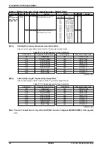
The prescaler output clock is used for the carrier signal generation clock. The prescaler generates 15 different
clocks, dividing the PCLK clock from 1/1 to 1/16K. One is selected by CGCLK[3:0] (D[7:4]/REMC_PSC regis-
ter).
∗
CGCLK[3:0]
: Carrier Generator Clock Select Bits in the REMC Prescaler Clock Select (REMC_PSC) Register
(D[7:4]/0x5341)
Table 21.3.1: Carrier generation clock selection
CGCLK[3:0]
Prescaler output clock
CGCLK[3:0]
Prescaler output clock
0xf
Reserved
0x7
PCLK-1/128
0xe
PCLK-1/16384
0x6
PCLK-1/64
0xd
PCLK-1/8192
0x5
PCLK-1/32
0xc
PCLK-1/4096
0x4
PCLK-1/16
0xb
PCLK-1/2048
0x3
PCLK-1/8
0xa
PCLK-1/1024
0x2
PCLK-1/4
0x9
PCLK-1/512
0x1
PCLK-1/2
0x8
PCLK-1/256
0x0
PCLK-1/1
(Default: 0x0)
For more information on prescaler control, refer to “9 Prescaler (PSC).”
Note: The prescaler must run before the REMC module.
The carrier H and L section lengths are set by REMCH[5:0] (D[5:0]/REMC_CARH register) and REMCL[5:0]
(D[5:0]/REMC_CARL register), respectively. These registers set a value corresponding to the number of clock
cycles selected above + 1.
∗
REMCH[5:0]
: H Carrier Length Setup Bits in the REMC H Carrier Length Setup (REMC_CARH) Register (D[5:0]/
0x5342)
∗
REMCL[5:0]
: L Carrier Length Setup Bits in the REMC L Carrier Length Setup (REMC_CARL) Register
(D[5:0]/0x5343)
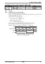
The carrier H and L section lengths can be calculated as follows:
REMCH
+
1
Carrier H section length = —————— [s]
clk_in
REMCL
+
1
Carrier L section length = —————— [s]
clk_in
REMCH: Carrier H section length register data value
REMCL: Carrier L section length register data value
clk_in:
Prescaler output clock frequency
The carrier signal is generated from these settings as shown in Figure 21.3.1.
Example: CGCLK[3:0] = 0x2 (PCLK-1/4), REMCH[5:0] = 2, REMCL[5:0] = 1
PCLK
PSC output clock
Count
Carrier
0
1
2
0
1
0
Carrier H section length
Carrier L section length
Figure 21.3.1: Carrier signal generation
Содержание S1C17001
Страница 1: ...Technical Manual S1C17001 CMOS 16 BIT SINGLE CHIP MICROCONTROLLER ...
Страница 31: ...3 MEMORY MAP AND BUS CONTROL 22 EPSON S1C17001 TECHNICAL MANUAL This page intentionally left blank ...
Страница 33: ...4 POWER SUPPLY VOLTAGE 24 EPSON S1C17001 TECHNICAL MANUAL This page intentionally left blank ...
Страница 63: ...6 INITERRUPT CONTROLLER 54 EPSON S1C17001 TECHNICAL MANUAL This page intentionally left blank ...
Страница 87: ...8 CLOCK GENERATOR CLG 78 EPSON S1C17001 TECHNICAL MANUAL This page intentionally left blank ...
Страница 91: ...9 PRESCALER PSC 82 EPSON S1C17001 TECHNICAL MANUAL This page intentionally left blank ...
Страница 133: ...11 16 BIT TIMER T16 124 EPSON S1C17001 TECHNICAL MANUAL This page intentionally left blank ...
Страница 185: ...14 8 BIT OSC1 TIMER T8OSC1 176 EPSON S1C17001 TECHNICAL MANUAL This page intentionally left blank ...
Страница 211: ...16 STOPWATCH TIMER SWT 202 EPSON S1C17001 TECHNICAL MANUAL This page intentionally left blank ...
Страница 219: ...17 WATCHDOG TIMER WDT 210 EPSON S1C17001 TECHNICAL MANUAL This page intentionally left blank ...
Страница 241: ...18 UART 232 EPSON S1C17001 TECHNICAL MANUAL This page intentionally left blank ...
Страница 277: ...20 I2 C 268 EPSON S1C17001 TECHNICAL MANUAL This page intentionally left blank ...
Страница 297: ...21 REMOTE CONTROLLER REMC 288 EPSON S1C17001 TECHNICAL MANUAL This page intentionally left blank ...
Страница 303: ...22 ON CHIP DEBUGGER DBG 294 EPSON S1C17001 TECHNICAL MANUAL This page intentionally left blank ...
Страница 313: ...25 PACKAGE 304 EPSON S1C17001 TECHNICAL MANUAL This page intentionally left blank ...

