6 INITERRUPT CONTROLLER
S1C17001 TECHNICAL MANUAL
EPSON
45
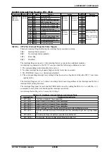
0x4306: External Interrupt Level Setup Register 0 (ITC_ELV0)
Register name Address
Bit
Name
Function
Setting
Init. R/W
Remarks
External
Interrupt Level
Setup Register 0
(ITC_ELV0)
0x4306
(16 bits)
D15–13
–
reserved
–
–
–
0 when being read.
D12
EITG1
P1 interrupt trigger mode
1 Level
0 Pulse
0
R/W Be sure to set to 1.
D11
–
reserved
–
–
–
0 when being read.
D10–8
EILV1[2:0]
P1 interrupt level
0 to 7
0x0
R/W
D7–5
–
reserved
–
–
–
0 when being read.
D4
EITG0
P0 interrupt trigger mode
1 Level
0 Pulse
0
R/W Be sure to set to 1.
D3
–
reserved
–
–
–
0 when being read.
D2–0
EILV0[2:0]
P0 interrupt level
0 to 7
0x0
R/W
D[15:13] Reserved
D12
EITG1: P1 Port Interrupt Trigger Mode Select Bit
Selects P1 port interrupt trigger mode. This should be set to 1 for the S1C17001.
1 (R/W): Level trigger mode
0 (R/W): Pulse trigger mode (default)
In pulse trigger mode, the ITC samples interrupt signals using system clock rising edges. When the
pulse High period is detected, the ITC sets the interrupt flag (EIFT
x
) to 1 and stops sampling that inter-
rupt signal. The ITC resumes interrupt signal sampling after the application program (interrupt process-
ing routine) resets the interrupt flag (EIFT
x
) to 0.
In level trigger mode, the ITC samples interrupt signals using system clock rising edges. When High
level is detected, the interrupt flag (EIFT
x
) is set to 1 and is subsequently reset to 0 when Low level is
detected. Interrupt flags (EIFT
x
) cannot be reset by writing 1 in this mode. The interrupt signal must be
maintained at High until the interrupt source module is accepted by the S1C17 core, and the interrupt
signal must then be cleared.
D11 Reserved
D[10:8]
EILV1[2:0]: P1 Port Interrupt Level Bits
Set the P1 port interrupt level (0 to 7). (Default: 0)
The S1C17 core does not accept interrupts with levels set lower than the PSR IL value.
The ITC uses the interrupt level when multiple interrupt factors occur simultaneously.
If multiple interrupts occur at the same time permitted by the interrupt enable bit, the ITC sends the in-
terrupt request with the highest level set by the ITC_ELV
x
and ITC_ILV
x
registers (0x4306 to 0x4314)
to the S1C17 core.
If multiple interrupt factors with the same interrupt level occur simultaneously, the interrupt with the
lowest vector number is processed first. The other interrupts are held until all have been accepted by the
S1C17 core in descending order of priority.
If an interrupt factor of higher priority occurs while the ITC outputs an interrupt request signal to the
S1C17 core (before acceptance by the S1C17 core), the ITC alters the vector number and interrupt level
signal to the setting details of the most recent interrupt. The immediately preceding interrupt is held.
D[7:5] Reserved
D4
EITG0: P0 Port Interrupt Trigger Mode Select Bit
Selects P0 port interrupt trigger mode. This should be set to 1 for the S1C17001.
1 (R/W): Level trigger mode
0 (R/W): Pulse trigger mode (default)
Refer to the EITG1 (D12) description.
D3 Reserved
D[2:0]
EILV0[2:0]: P0 Port Interrupt Level Bits
Set the P0 port interrupt level (0 to 7). (Default: 0)
Refer to the EILV1[2:0] (D[10:8]) description.
Содержание S1C17001
Страница 1: ...Technical Manual S1C17001 CMOS 16 BIT SINGLE CHIP MICROCONTROLLER ...
Страница 31: ...3 MEMORY MAP AND BUS CONTROL 22 EPSON S1C17001 TECHNICAL MANUAL This page intentionally left blank ...
Страница 33: ...4 POWER SUPPLY VOLTAGE 24 EPSON S1C17001 TECHNICAL MANUAL This page intentionally left blank ...
Страница 63: ...6 INITERRUPT CONTROLLER 54 EPSON S1C17001 TECHNICAL MANUAL This page intentionally left blank ...
Страница 87: ...8 CLOCK GENERATOR CLG 78 EPSON S1C17001 TECHNICAL MANUAL This page intentionally left blank ...
Страница 91: ...9 PRESCALER PSC 82 EPSON S1C17001 TECHNICAL MANUAL This page intentionally left blank ...
Страница 133: ...11 16 BIT TIMER T16 124 EPSON S1C17001 TECHNICAL MANUAL This page intentionally left blank ...
Страница 185: ...14 8 BIT OSC1 TIMER T8OSC1 176 EPSON S1C17001 TECHNICAL MANUAL This page intentionally left blank ...
Страница 211: ...16 STOPWATCH TIMER SWT 202 EPSON S1C17001 TECHNICAL MANUAL This page intentionally left blank ...
Страница 219: ...17 WATCHDOG TIMER WDT 210 EPSON S1C17001 TECHNICAL MANUAL This page intentionally left blank ...
Страница 241: ...18 UART 232 EPSON S1C17001 TECHNICAL MANUAL This page intentionally left blank ...
Страница 277: ...20 I2 C 268 EPSON S1C17001 TECHNICAL MANUAL This page intentionally left blank ...
Страница 297: ...21 REMOTE CONTROLLER REMC 288 EPSON S1C17001 TECHNICAL MANUAL This page intentionally left blank ...
Страница 303: ...22 ON CHIP DEBUGGER DBG 294 EPSON S1C17001 TECHNICAL MANUAL This page intentionally left blank ...
Страница 313: ...25 PACKAGE 304 EPSON S1C17001 TECHNICAL MANUAL This page intentionally left blank ...


