7 OSCILLATOR CIRCUIT (OSC)
58
EPSON
S1C17001 TECHNICAL MANUAL
7.3 OSC1 Oscillator Circuit
The OSC1 oscillator circuit generates a (typ.) 32.768 kHz sub-clock.
The OSC1 clock is generally used as the timer operation clock (for the clock timer, stopwatch timer, watchdog tim-
er, and 8-bit OSC1 timer). It reduces power consumption and can be used as the system clock instead of the OSC3
clock when no high-speed processing is required.
The oscillator circuit is crystal-based. The oscillator circuit also allows use of an external clock input.
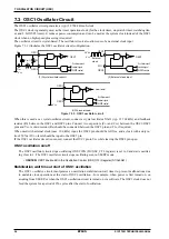
Figure 7.3.1 illustrates the OSC1 oscillator circuit configuration.
Low level
OSC1
External
clock
N.C.
V
SS
LV
DD
OSC1
(1) Crystal oscillator circuit
V
SS
(3) When not used
(2) External clock input
V
SS
C
D1
C
G1
X'tal1
R
f
R
d
OSC2
OSC1
OSC2
OSC1
OSC2
OSC1
Oscillator circuit
control signal
Oscillator circuit
control signal
SLEEP control
Oscillator circuit
control signal
SLEEP control
SLEEP control
Figure 7.3.1: OSC1 oscillator circuit
When this is used as a crystal oscillator circuit, connect a crystal oscillator X’tal1 (typ. 32.768 kHz) and feedback
resistor (R
f
) between the OSC1 and OSC2 pins. Connect two capacitors (C
G1
and C
D1
) between the OSC1/OSC2
pins and V
SS
. A drain resistor (R
d
) should be connected between the OSC2 pin and C
D1
, if required.
When used with external clock (max. 100 kHz) input, the OSC2 pin should be left free, and a clock with a duty ra-
tio of 50% at LV
DD
level should be input to the OSC1 pin.
If the OSC1 oscillator circuit is not used, connect the OSC1 pin to V
SS
while leaving the OSC2 pin open.
OSC1 oscillation on/off
The OSC1 oscillator circuit stops oscillating if OSC1EN (D1/OSC_CTL register) is set to 0 and starts oscillat-
ing if set to 1. The OSC1 oscillator circuit stops oscillating even in SLEEP mode.
∗
OSC1EN
: OSC1 Enable Bit in the Oscillation Control (OSC_CTL) Register (D1/0x5061)
Stabilization wait time at start of OSC1 oscillation
The OSC1 oscillator circuit incorporates an oscillation stabilization wait timer to prevent malfunctions due
to unstable clock operations at the start of OSC1 oscillation—for example, when power is first turned on, on
awaking from SLEEP, or when the OSC1 oscillation circuit is turned on via software. The OSC1 clock does not
feed the system for a period of 256 cycles after the start of oscillation.
Содержание S1C17001
Страница 1: ...Technical Manual S1C17001 CMOS 16 BIT SINGLE CHIP MICROCONTROLLER ...
Страница 31: ...3 MEMORY MAP AND BUS CONTROL 22 EPSON S1C17001 TECHNICAL MANUAL This page intentionally left blank ...
Страница 33: ...4 POWER SUPPLY VOLTAGE 24 EPSON S1C17001 TECHNICAL MANUAL This page intentionally left blank ...
Страница 63: ...6 INITERRUPT CONTROLLER 54 EPSON S1C17001 TECHNICAL MANUAL This page intentionally left blank ...
Страница 87: ...8 CLOCK GENERATOR CLG 78 EPSON S1C17001 TECHNICAL MANUAL This page intentionally left blank ...
Страница 91: ...9 PRESCALER PSC 82 EPSON S1C17001 TECHNICAL MANUAL This page intentionally left blank ...
Страница 133: ...11 16 BIT TIMER T16 124 EPSON S1C17001 TECHNICAL MANUAL This page intentionally left blank ...
Страница 185: ...14 8 BIT OSC1 TIMER T8OSC1 176 EPSON S1C17001 TECHNICAL MANUAL This page intentionally left blank ...
Страница 211: ...16 STOPWATCH TIMER SWT 202 EPSON S1C17001 TECHNICAL MANUAL This page intentionally left blank ...
Страница 219: ...17 WATCHDOG TIMER WDT 210 EPSON S1C17001 TECHNICAL MANUAL This page intentionally left blank ...
Страница 241: ...18 UART 232 EPSON S1C17001 TECHNICAL MANUAL This page intentionally left blank ...
Страница 277: ...20 I2 C 268 EPSON S1C17001 TECHNICAL MANUAL This page intentionally left blank ...
Страница 297: ...21 REMOTE CONTROLLER REMC 288 EPSON S1C17001 TECHNICAL MANUAL This page intentionally left blank ...
Страница 303: ...22 ON CHIP DEBUGGER DBG 294 EPSON S1C17001 TECHNICAL MANUAL This page intentionally left blank ...
Страница 313: ...25 PACKAGE 304 EPSON S1C17001 TECHNICAL MANUAL This page intentionally left blank ...

