20 I
2
C
S1C17001 TECHNICAL MANUAL
EPSON
255
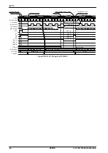
Data receipt control
The procedure for receiving data is described below. The start condition must first be generated before receiv-
ing data, and the slave address sent with the transfer direction bit set to 1.
To receive data, set RXE (D10/I2C_DAT register) to 1 for receiving 1 byte.
TXE (D9/I2C_DAT register) is set to 1 when sending the slave address, but RXE can also be set to 1 at the
same time. If both TXE and RXE are set to 1, TXE takes priority.
∗
RXE
: Receive Execution Bit in the I
2
C Data (I2C_DAT) Register (D10/0x4344)
When the RXE bit is set to 1, allowing receiving to start, the I
2
C module starts outputting the clock from the
SCL pin with the SDA line at high impedance. The data is loaded to the shift register in sequence at the clock
rising edge, with the MSB leading.
RXE is reset to 0 when D6 is loaded.
The receive data is loaded to RTDT[7:0] once the 8-bit data has been received in the shift register. The I
2
C
module includes two status bits for receive control: RBRDY (D11/I2C_DAT register) and RBUSY (D9/
I2C_CTL register).
∗
RBRDY
: Receive Buffer Ready Bit in the I
2
C Data (I2C_DAT) Register (D11/0x4344)
∗
RBUSY
: Receive Busy Flag in the I
2
C Control (I2C_CTL) Register (D9/0x4342)
The RBRDY flag indicates the receive data status. This flag becomes 1 when the data received in the shift
register is loaded to RTDT[7:0] and reverts to 0 when the receive data is read out from RTDT[7:0]. Interrupts
can also be generated once the flag value becomes 1, so either use this interrupt or read the receive data to
determine the presence of valid receive data in RTDT[7:0] by inspecting the RBRDY flag. If the subsequent
data is received before RTDT[7:0] is read out, the newly received data overwrites the data already received in
RTDT[7:0].
The RBUSY flag indicates the receiving operation status. This flag is 1 when receiving starts and reverts to 0
when the data is received. It also reverts to 0 for the Wait state. Inspect the flag to determine whether the I
2
C
module is currently receiving or in standby.
The
I
2
C module outputs 9 clocks with each data receipt. In the 9th clock cycle, an ACK or NACK is sent to the
slave. The bit state sent can be set in RTACK (D8/I2C_DAT register). To send ACK, set RTACK to 0. To send
NACK, set RTACK to 1.
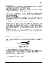
Data transfer end (Stop condition generation)
To end data transfers after all data has been transferred, the I
2
C master (this module) must generate a stop con-
dition. This stop condition applies when the SCL line is maintained at High and the SDA line changes from
Low to High.
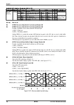
SDA (output)
SCL (output)
Stop condition
Figure 20.5.4: Stop condition
The stop condition is generated by setting STP (D1/I2C_CTL register) to 1.
∗
STP
: Stop Control Bit in the I
2
C Control (I2C_CTL) Register (D1/0x4342)
The stop condition described above is generated if STP is 1 and TXE (D9/I2C_register), RXE (D10/I2C_DAT
register), and STRT (D0/I2C_CTL register) are set to 0 when data transfer is complete (including ACK trans-
fer). The I
2
C bus will then be free. STP is automatically reset to 0 if the stop condition is generated.
STP will be disabled if any of TXE, RXE, or STRT is 1.
The
I
2
C module does not support repeated start condition. The stop condition cannot be omitted before generat-
ing the start condition for the subsequent data transfer.
Содержание S1C17001
Страница 1: ...Technical Manual S1C17001 CMOS 16 BIT SINGLE CHIP MICROCONTROLLER ...
Страница 31: ...3 MEMORY MAP AND BUS CONTROL 22 EPSON S1C17001 TECHNICAL MANUAL This page intentionally left blank ...
Страница 33: ...4 POWER SUPPLY VOLTAGE 24 EPSON S1C17001 TECHNICAL MANUAL This page intentionally left blank ...
Страница 63: ...6 INITERRUPT CONTROLLER 54 EPSON S1C17001 TECHNICAL MANUAL This page intentionally left blank ...
Страница 87: ...8 CLOCK GENERATOR CLG 78 EPSON S1C17001 TECHNICAL MANUAL This page intentionally left blank ...
Страница 91: ...9 PRESCALER PSC 82 EPSON S1C17001 TECHNICAL MANUAL This page intentionally left blank ...
Страница 133: ...11 16 BIT TIMER T16 124 EPSON S1C17001 TECHNICAL MANUAL This page intentionally left blank ...
Страница 185: ...14 8 BIT OSC1 TIMER T8OSC1 176 EPSON S1C17001 TECHNICAL MANUAL This page intentionally left blank ...
Страница 211: ...16 STOPWATCH TIMER SWT 202 EPSON S1C17001 TECHNICAL MANUAL This page intentionally left blank ...
Страница 219: ...17 WATCHDOG TIMER WDT 210 EPSON S1C17001 TECHNICAL MANUAL This page intentionally left blank ...
Страница 241: ...18 UART 232 EPSON S1C17001 TECHNICAL MANUAL This page intentionally left blank ...
Страница 277: ...20 I2 C 268 EPSON S1C17001 TECHNICAL MANUAL This page intentionally left blank ...
Страница 297: ...21 REMOTE CONTROLLER REMC 288 EPSON S1C17001 TECHNICAL MANUAL This page intentionally left blank ...
Страница 303: ...22 ON CHIP DEBUGGER DBG 294 EPSON S1C17001 TECHNICAL MANUAL This page intentionally left blank ...
Страница 313: ...25 PACKAGE 304 EPSON S1C17001 TECHNICAL MANUAL This page intentionally left blank ...


