Chapter 3—Installation and Wiring
40
Power Xpert C445 Global Motor Management Relay
MN042003EN—January 2019
www.eaton.com
The outputs are relay contacts and wired as follows.
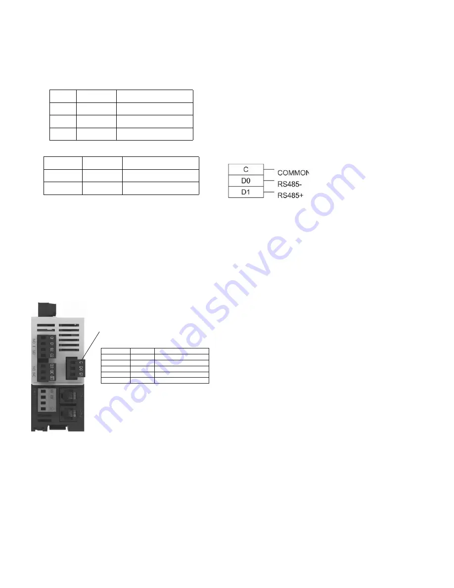
Figure 49. 4-Point Form A (NO) Output Connector
Figure 50. 3-Point Form C (NO/NC) Output Connector
Optional RS-485 Port
If the C445 includes an RS-485 port on the Base Control
Module and there is not an optional Ethernet or PROFIBUS
Communication Card installed, the Modbus address and
Baud Rate for this port is assigned with the DIP Switches on
the Base Control Module.
If an optional PROFIBUS Card is installed, the DIP Switches
on the Base Control Module double as the node address for
the RS-485 Modbus port and the PROFIBUS slave module.
Figure 51. Modbus Serial Connection
If an optional Ethernet Card is installed, the DIP Switches on
the Base Control Module are dedicated to the Ethernet
Card’s IP address. In this case, the RS-485 port must be
configured via the Power Xpert
in
Control Software or via
Modbus commands form a Modbus master. The Modbus
Register map is in
Appendix D
.
Note that even if there is no optional Ethernet or PROFIBUS
communication card installed, the DIP Switches can be set to
allow the Modbus address to be set with the configuration
software.
Figure 52. RS-485 Port
Notes
●
Shield shall be Earthed externally
●
Shield should NOT be connected to any of these three
terminals
●
Wiring must meet PELV requirements
Q1
Output 1
Normally Open (NO)
Q1
Output 1
Normally Open (NO)
Q2
Output 2
Normally Open (NO)
Q2
Output 2
Normally Open (NO)
Q3
Output 3
Normally Open (NO)
C
Output 3
Common
Q3 (Not)
Output 3
Normally Closed (NC)
Setting
Default
Range
Address
1
1 to 247
Baud Rate
19200
9600, 19200, 115200
Stop Bits
1
1 or 2
Parity
Even
Even or Odd
Mode
RTU
RTU or ASCII
Modbus Serial Port
(RS-485)


