Chapter 9—C445 Logic Engine and Expansion I/O
204
Power Xpert C445 Global Motor Management Relay
MN042003EN—January 2019
www.eaton.com
Modbus TCP and RS-485 Modbus
The digital I/O is stored in the following registers and is also
mapped based on the position of each digital module to the
right of the adapter.
Digital Inputs: registers 2255-2262
Digital Outputs: registers 2263-2270
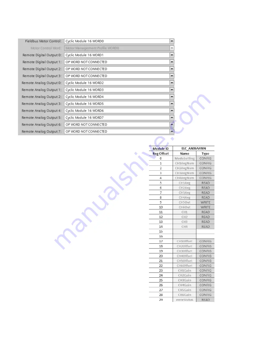
The digital I/O modules are not configurable. The analog
I/O modules do need to be configured. In addition, these
modules have 30 registers that are mapped to the following
registers, based on their position when connected to the
ELC-CARS485 adapter module. The first analog module to
the right of the adapter is mapped first and so on, with a
maximum of 8 analog modules. The Modbus registers
that contain the data for the 30 registers for each module
are as follows:
Analog module #1: registers 2015-2044
Analog module #2: registers 2045-2074
Analog module #3: registers 2075-2104
Analog module #4: registers 2105-2134
Analog module #5: registers 2135-2164
Analog module #6: registers 2165-2194
Analog module #7: registers 2195-2224
Analog module #8: registers 2225-2254
The data contained in the 30 registers for each type of analog
module is shown below. “ModeSetting” is the configuration
word for each analog module type and can be configured
using the Expansion I/O Configurator page in the Logic
Engine programming software. This determines the type of
analog I/O for each module (current or voltage) and the type
of thermocouple inputs for the thermocouple input module.


