82
v
Drum Driving Section
chap.2
Description
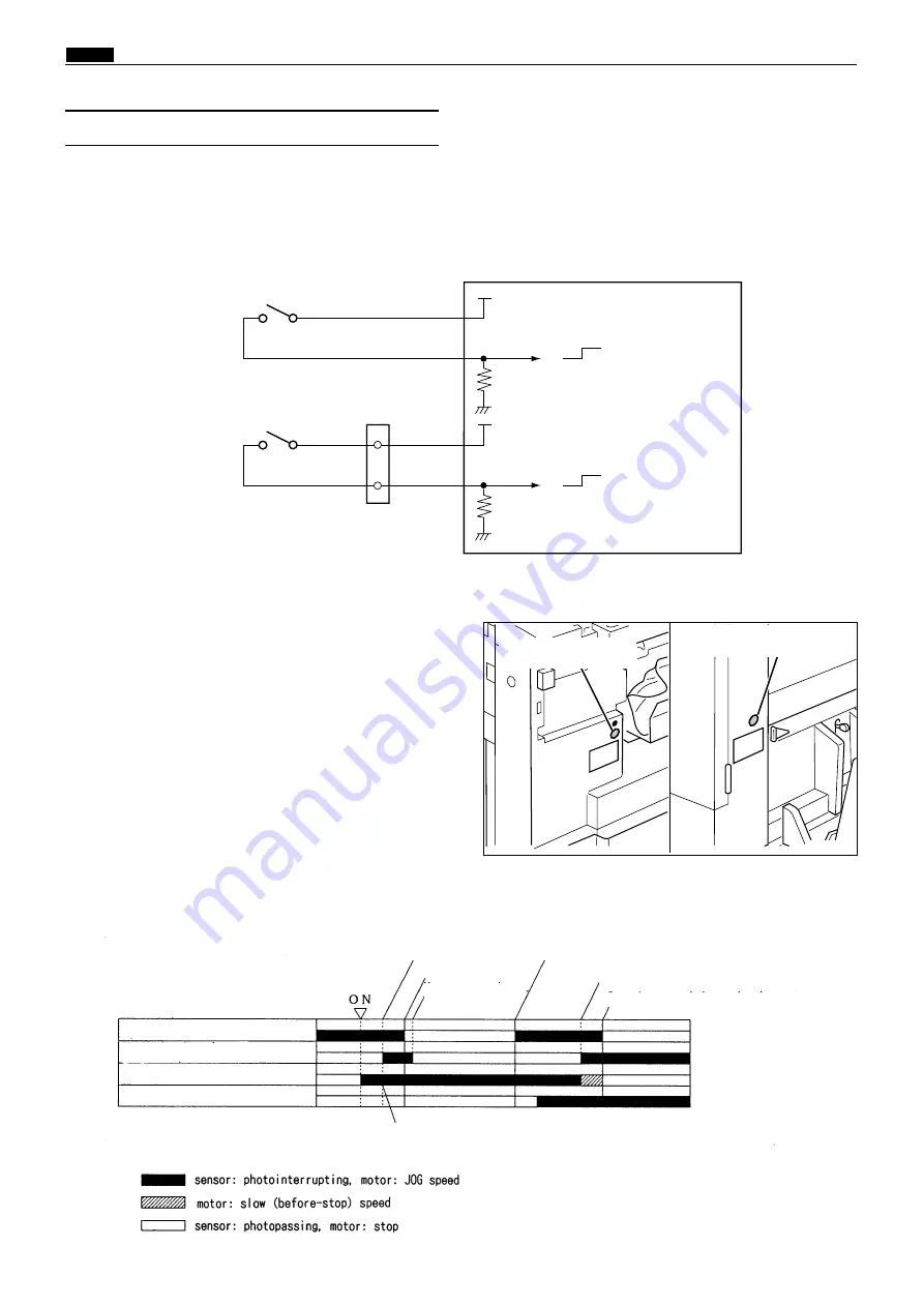
The drum rotates as long as the
JOG switch (drum rotation switch)
is pressed (within one rotation) and stops
at the stop position with a beep.When the drum stops there, the LED mounted on the JOG switch 1 will light up.
In the normal state, the drum rotates (within one
rotation) when the
JOG switch (drum rotation
switch)
is kept pressed and the drum stops at the
stop position, reducing the speed to the slow
(before-stop) speed at the first master removal
position.
When the P-roll sensor is in the photopassing
state (press roller ON) at the first plate
detachment position, the drum passes the stop
position without reducing the speed.
Drum rotation 1 switch
Drum rotation 2 switch
Purple
Purple
CN4-8
-9
5V
5V
0
Light green
Light green
CN21-5
-6
5V
5V
0
1
2
M a i n P C B u n i t
Circuit
(3) JOG Switch 1,2 (Drum Rotation Switch 1,2)
JOG switch
(Drum rotation switch)
JOG switch (drum rotation switch) (SW3)
440355
440W21e
2
When the JOG Switch (Drum Rotation Switch) Is
Pressed Down
Sequence of Operation
Drum stop/JAM detect position sensor
Master detach position
Master attach
position
Drum stop position
JAM detect position
Master detach position :
drum reduce the speed
Drum stop position : drum stops
Master attach/detach position
Main motor
P-roll sensor
When the P-roll sensor is in the photopassing state(press roller ON),
the drum dose not reduce the speed at the master detach position.
JOG switch
(Drum rotation switch)
Содержание Duprinter DP-330
Страница 9: ......
Страница 11: ......
Страница 18: ...c Dimensions chap 1 17 MEMO...
Страница 24: ...4 8 2A 2B 2C 44000A1e b Part Names and Their Functions chap 1 23...
Страница 152: ...151 MEMO...
Страница 193: ...192 MEMO...
Страница 328: ...327 x Overall Wiring Layout chap 8 14 2 Overall Wiring Layout 2 Overall Wiring Layout 2 Drive PCB 1 2 O...
Страница 329: ...328 x Overall Wiring Layout chap 8 15 Overall Wiring Layout 2 Drive PCB 2 2...


