120
x
Scanner Section
chap.3
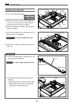
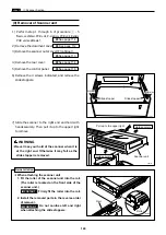
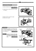
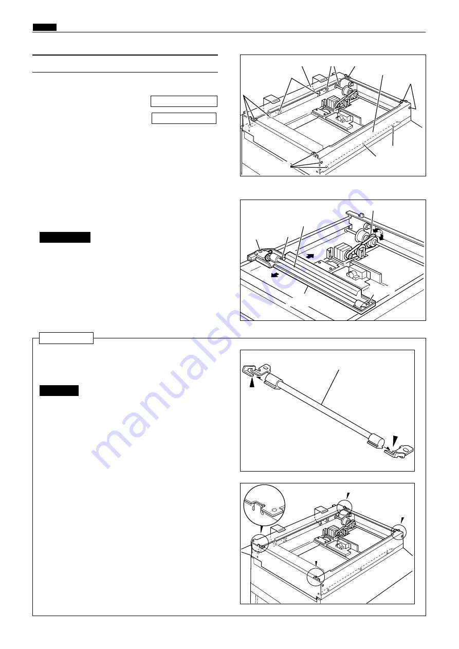
(5) Removal of Lamp Unit
440047
Scanner R bracket
440048
5) Turn the timing pulley, and move Slider A to the
position shown in the diagram.
Screw
Timing pulley
24S023
440049
Lamp unit
Notch
1) Carry out (1) through (3) above.
2) Remove the scanner cover(L,R).
3) Slide the scanner forward and backward to
remove the 7 screws securing the scanner F
bracket. Remove the scanner F bracket.
4) Remove the 8 spacers indicated, and remove the
scanner R bracket.
\
See page 113
\
See page 118
Do not move Slider A by hand.
IMPORTANT :
6) Remove the 3 screws indicated, and remove the
lamp unit.
The lamp is fragile; handle it with care.
IMPORTANT :
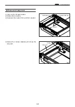
Reinstallation
¡
Insert the slotted parts of the lamp unit into
the grooves on the brackets.
¡
When attaching the scanner's front and rear
brackets:
1. Align the notches on the left and right sides.
2. When attaching the scanner's rear bracket,
be careful to not pinch the wiring.
Screw
Screw
Screws
Screws
Screw
Screw
Screws
Screws
Screws
Scanner F
bracket
Screw
Lamp unit
Bracket groove
Bracket groove
Notch
Notch
Notch
Slider A
Содержание Duprinter DP-330
Страница 9: ......
Страница 11: ......
Страница 18: ...c Dimensions chap 1 17 MEMO...
Страница 24: ...4 8 2A 2B 2C 44000A1e b Part Names and Their Functions chap 1 23...
Страница 152: ...151 MEMO...
Страница 193: ...192 MEMO...
Страница 328: ...327 x Overall Wiring Layout chap 8 14 2 Overall Wiring Layout 2 Overall Wiring Layout 2 Drive PCB 1 2 O...
Страница 329: ...328 x Overall Wiring Layout chap 8 15 Overall Wiring Layout 2 Drive PCB 2 2...


