124
x
Scanner Section
chap.3
440166
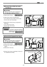
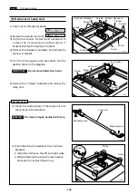
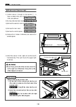
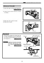
Slide stopper
Slide stopper
Screw
Screw
440167
Scanner unit
Hold securely
Hold securely
Pull up to the upper right
WARNING
¡
Never lose your hold of the scanner when it is
at the right end. Otherwise it may fall as the
slide stopper is removed.
¡
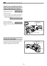
When attaching the scanner unit
1. Fit the roller of the scanner unit into the rail.
(The roller is located on the front side of the
scanner unit.)
Firmly fit the roller into the rail.
2. Install the removed parts in the reverse order
of removal.
Do not confuse left and right
when attaching the slide stoppers.
IMPORTANT :
IMPORTANT :
Reinstallation
1) Perform step 1 through 6 of procedure
z
- 5
“Remove of Main PCB unit, P-memory PCB unit, Battery
PCB unit and Master”
.
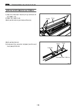
2) Remove the document cover.
3) Remove the scanner outer cover(Front,Rear).
4) Remove the rear cover.
5) Remove the control panel.
\
See page 116
\
See page 114
\
See page 113
\
See page 112
\
See page 114
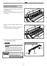
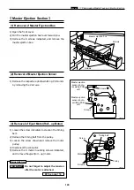
6) Remove the 4 screws indicated, and remove the
slide stoppers.
7) Slide the scanner to the right end and hold with
hands securely. Then pull it up to the upper right
to remove
Rail
440169
Roller
(9) Removal of Scanner unit
Содержание Duprinter DP-330
Страница 9: ......
Страница 11: ......
Страница 18: ...c Dimensions chap 1 17 MEMO...
Страница 24: ...4 8 2A 2B 2C 44000A1e b Part Names and Their Functions chap 1 23...
Страница 152: ...151 MEMO...
Страница 193: ...192 MEMO...
Страница 328: ...327 x Overall Wiring Layout chap 8 14 2 Overall Wiring Layout 2 Overall Wiring Layout 2 Drive PCB 1 2 O...
Страница 329: ...328 x Overall Wiring Layout chap 8 15 Overall Wiring Layout 2 Drive PCB 2 2...


