117
z
Exterior
chap.3
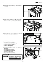
1) Remove the front cover.
2) Remove the connectors and terminals of.
¡
Drive PCB Unit (14 connectors,12 terminals)
¡
DC-DC PCB Unit (4 connectors)
3) Remove the mounting screws, and replace the
PCB units.
¡
Drive PCB Unit: 6 screws
¡
DC-DC PCB Unit: 4 screws
\
See page 112
440041
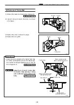
(8) Removal of Drive PCB Unit and DC -
DC PCB Unit
Drive PCB unit
Screws
Screws
DC-DC PCB
Unit
Screws
WARNING
¡
Always remove the power cord plug from
the outlet before replacing a PCB Unit.
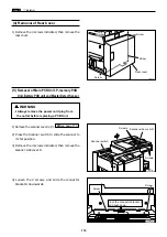
1) Remove the front cover.
2) Remove the 3 screws indicated,and remove the
bracket.
3) Remove the 12 terminals.
\
See page 112
440043
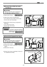
(9) Removal of DC Regulated Power Supply
Screws
Regulated power supply
WARNING
¡
Always remove the power cord plug from
the outlet before replacing a PCB Unit.
440042
Screws
4) Remove the 4 screws indicated,and remove the
DC regulated power supply.
Terminals
Bracket
Screws
Screws
Screw
VR1
Reinstallation
Do not forget to adjust the double feed
detection sensor after the drive PCB
unit is changed.
\
See page 167
IMPORTANT :
Содержание Duprinter DP-330
Страница 9: ......
Страница 11: ......
Страница 18: ...c Dimensions chap 1 17 MEMO...
Страница 24: ...4 8 2A 2B 2C 44000A1e b Part Names and Their Functions chap 1 23...
Страница 152: ...151 MEMO...
Страница 193: ...192 MEMO...
Страница 328: ...327 x Overall Wiring Layout chap 8 14 2 Overall Wiring Layout 2 Overall Wiring Layout 2 Drive PCB 1 2 O...
Страница 329: ...328 x Overall Wiring Layout chap 8 15 Overall Wiring Layout 2 Drive PCB 2 2...


