150
m
Drum Section
chap.3
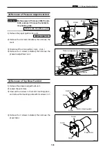
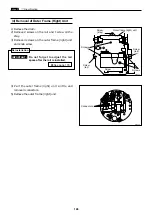
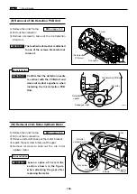
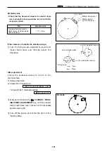
(9) Removal of Ink Detection PCB Unit
1) Remove the inner frame.
2) Pull out the connector.
3) Remove 2 screws to take out the ink detection
PCB Unit.
The toothed lock washer is attached
to one of the screws. Be careful not
to lose it.
IMPORTANT :
\
See page 148
Confirm that the detection needle
is vertical with the PCB Unit and
does not contact anywhere, when
installing the Ink detection PCB
Unit.
IMPORTANT :
Reinstallation
Screw
Connector
Screw
440097new
Ink detection
PCB unit
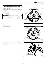
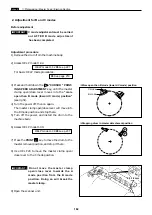
(10) Removal of Ink Roller Up/Down Motor
1) Remove the inner frame.
2) Pull out the 2 connectors.
3) Remove 2 screws to take out the motor bracket.
4) Loosen the set screw to take out the gear.
5) Remove 3 screws to take out the ink roller
up/down motor.
\
See page 148
Screws
Connectors
440165new
Ink detection PCB unit
Ink roller
Squeegee roller
Detection
needle
440098
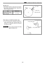
Leave a space of 3 mm in the
section shown in the figure
when attaching the gear after
replacing the motor.
Reinstallation
IMPORTANT :
Screws
Ink roller
up/down motor
Cover
Gear
Screw
Set screw
3mm
Содержание Duprinter DP-330
Страница 9: ......
Страница 11: ......
Страница 18: ...c Dimensions chap 1 17 MEMO...
Страница 24: ...4 8 2A 2B 2C 44000A1e b Part Names and Their Functions chap 1 23...
Страница 152: ...151 MEMO...
Страница 193: ...192 MEMO...
Страница 328: ...327 x Overall Wiring Layout chap 8 14 2 Overall Wiring Layout 2 Overall Wiring Layout 2 Drive PCB 1 2 O...
Страница 329: ...328 x Overall Wiring Layout chap 8 15 Overall Wiring Layout 2 Drive PCB 2 2...

