168
c
Paper Feed Section
chap.4
ADJUST
PRINT POS.
OK
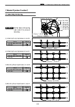
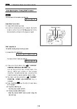
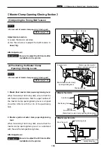
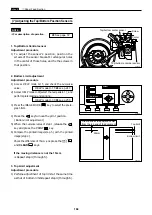
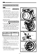
(7) Adjusting the Top/Bottom Position Sensors
¡
For description of operation.
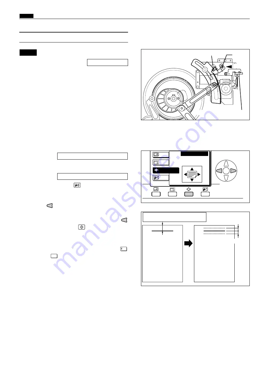
1. Top/Bottom Central sensor
Adjustment procedure
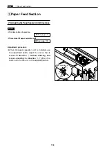
1) To adjust the sensor's position, position the
screws of the sensor bracket's rectangular holes
in the center of those holes, and fix the screws in
that position.
NOTE :
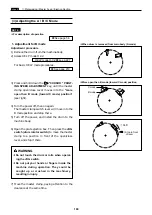
2. Bottom Limit adjustment
Adjustment procedure
1) Access HELP mode
H-15
, and check the
numerical
value
.
2) Access HELP mode
H-30
(select the
test pattern 1
), and
perform platemaking and printing.
3) Press the
IMAGE MODE
key to select the
photo-
graph
item.
4) Press the
key to move the print position.
(
Bottom limit adjustment
)
5) When the
numerical value
of step 1 ,release the
key and press the
key.
6) Compare the printed image( step 5 ) with the printed
image( step 2 ).
Check the difference of
15mm ,and
press the [
=
]
and
CLEAR
keys.
If the moving distance is not the 15mm
¡
Repeat step 4) through 5).
C
HELP mode H-30
\
see p.259
HELP mode H-15
\
see p.243
\
See page 72
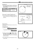
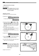
Draw a line at the position 30mm
from the top end of the document
30mm
440352
440162
Top limit
Bottom limit
440122
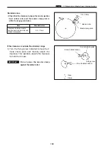
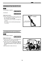
Screw
Center
Top/bottom center sensor
Top/bottom encorder sensor
3. Top Limit adjustment
Adjustment procedure
1) Perfome adjustment of top limit at the same time
as that of bottom limit.Repeat step 4) through 6).
Содержание Duprinter DP-330
Страница 9: ......
Страница 11: ......
Страница 18: ...c Dimensions chap 1 17 MEMO...
Страница 24: ...4 8 2A 2B 2C 44000A1e b Part Names and Their Functions chap 1 23...
Страница 152: ...151 MEMO...
Страница 193: ...192 MEMO...
Страница 328: ...327 x Overall Wiring Layout chap 8 14 2 Overall Wiring Layout 2 Overall Wiring Layout 2 Drive PCB 1 2 O...
Страница 329: ...328 x Overall Wiring Layout chap 8 15 Overall Wiring Layout 2 Drive PCB 2 2...

