


177
m
Drum Section
chap.4
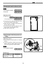
(3) Adjusting the Master Clamp
¡
For removal.
When the master clamp parallelism is not proper,
the master creases. When the master clamp is not
flat, the master is easily removed and creases.
* Adjust the master clamp with the set screw on the
operation side.
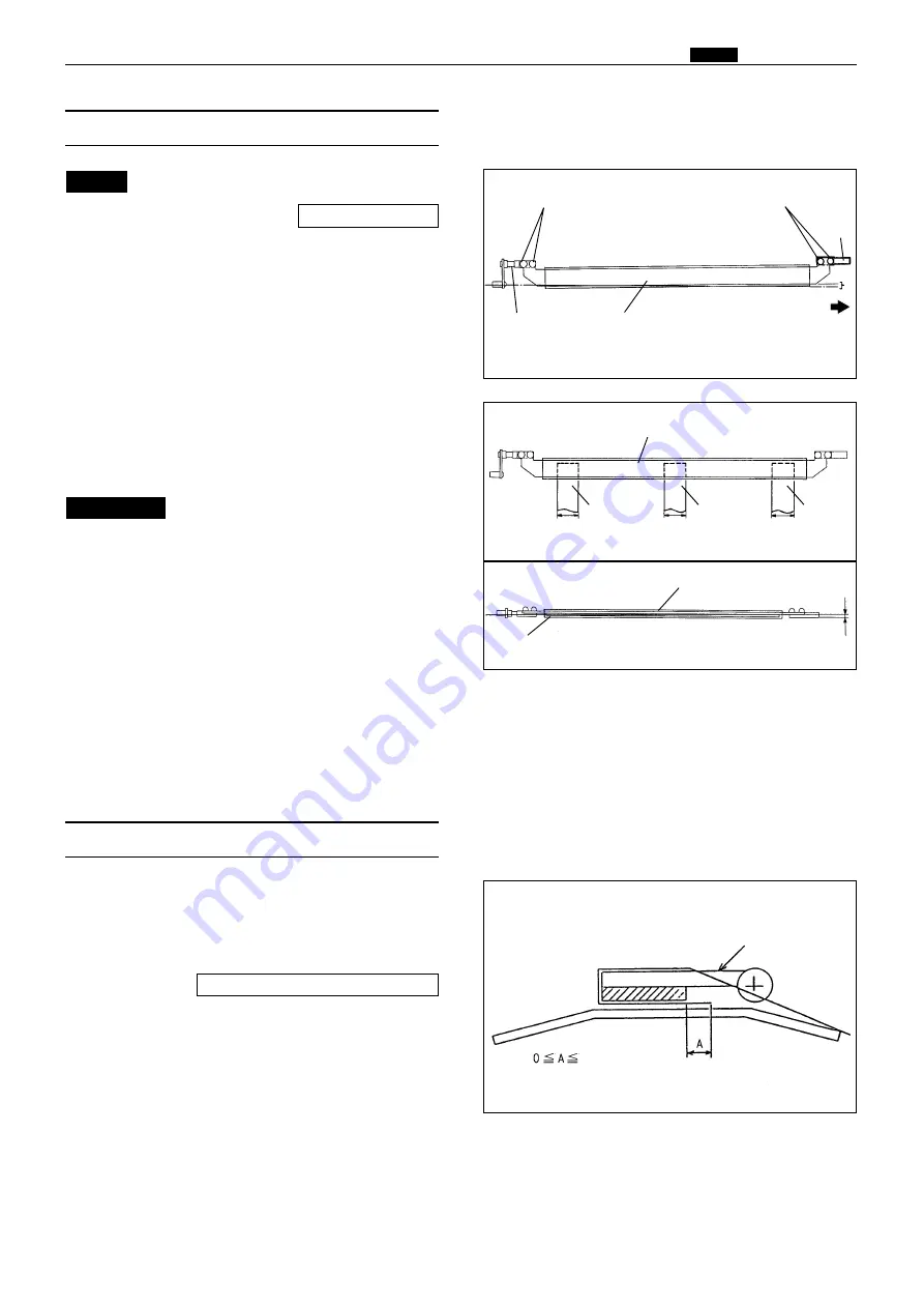
1. Adjusting the clamp parallelism
Adjustment procedure
1) Loosen the set screws on the clamp plate and
shaft to adjust the parallelism.
NOTE :
Loosen the set screw on the
operation side to adjust.
But do not loosen the set screw on
the lever shaft.
IMPORTANT :
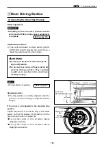
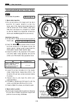
2. Adjusting the clamp flatness
Adjustment procedure
1) Cut the master, leaving 20mm wide piece at
three places, both sides and center. Have the
clamp plate grip the three sections.
2) When the resistance for pulling the master out
is not stable, rotate the clamp screw to adjust.
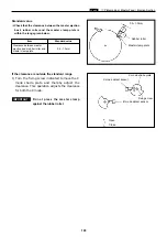
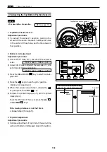
(4) Adjusting the Master Clamp Section
Adjustment procedure
1) Adjust with HELP mode 29 so that the clamp
amount of the master (A section in the figure) is
0~2mm
with the master attached.
2) After HELP 29 adjustment, press the perform
master set movement once. (Be sure to remove
all paper scraps.) Then perform platemaking,
and check the gripper margin.
Set screws
Clamp plate
Clamp plate
Clamp plate
Rubber magnet
Torsion
Master
20mm
Master
Master
Operation side
Lever shaft
Set screws (for adjustment)
shaft
\
See page 144
20mm
20mm
HELP mode H-29
\
see p.258
Master clamp
2mm
Содержание Duprinter DP-330
Страница 9: ......
Страница 11: ......
Страница 18: ...c Dimensions chap 1 17 MEMO...
Страница 24: ...4 8 2A 2B 2C 44000A1e b Part Names and Their Functions chap 1 23...
Страница 152: ...151 MEMO...
Страница 193: ...192 MEMO...
Страница 328: ...327 x Overall Wiring Layout chap 8 14 2 Overall Wiring Layout 2 Overall Wiring Layout 2 Drive PCB 1 2 O...
Страница 329: ...328 x Overall Wiring Layout chap 8 15 Overall Wiring Layout 2 Drive PCB 2 2...


