115
z
Exterior
chap.3
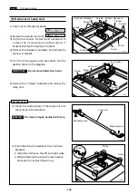
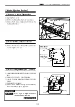
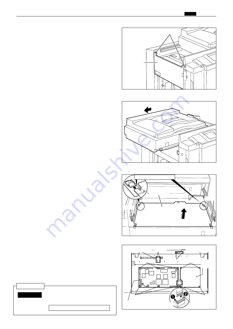
8) Remove the connectors of.
¡
Battery PCB Unit (connector)
¡
P-memory PCB unit (4 connectors)
¡
Main PCB unit (17 connectors)
¡
Master sensor(connector)
9) Remove the mounting screws, and replace the
PCB units.
¡
Battery PCB Unit: 2 screws
¡
P-memory PCB unit: 4 screws
¡
Main PCB unit: 6 screws
¡
Master detect sensor: 2 screws
440105
Screw
Screw
Board cover
440037
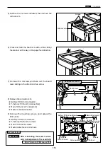
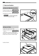
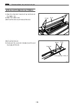
5) Remove the 2 screws indicated, then remove the
side cover L.
Screws
Side cover L
440038
6) Press and hold the Scanner switch while sliding
the scanner all the way in the paper feed direction.
440039
Main PCB unit
Battery PCB unit
Screws
Screws
Screws
Screws
P-memory
PCB unit
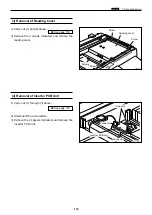
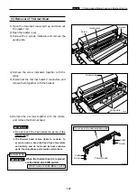
7) Remove the 4 screws,and take out the board
cover sliding in the direction of an arrow.
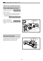
Master detect sensor
Screws
Screws
Pull upwards
Pull out
Reinstallation: insert
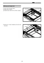
After reinstalling the master sensor,
carry out adjustment of its sensitivity.
HELP mode H-07
\
see p.235
IMPORTANT :
Reinstallation
Содержание Duprinter DP-330
Страница 9: ......
Страница 11: ......
Страница 18: ...c Dimensions chap 1 17 MEMO...
Страница 24: ...4 8 2A 2B 2C 44000A1e b Part Names and Their Functions chap 1 23...
Страница 152: ...151 MEMO...
Страница 193: ...192 MEMO...
Страница 328: ...327 x Overall Wiring Layout chap 8 14 2 Overall Wiring Layout 2 Overall Wiring Layout 2 Drive PCB 1 2 O...
Страница 329: ...328 x Overall Wiring Layout chap 8 15 Overall Wiring Layout 2 Drive PCB 2 2...


