


CLUTCHES AND TRANSMISSIONS 7-29
TURBO HYDRA-M ATIC 400 T R AN SM ISSIO N
INDEX
Page
General D escription................................................................................ ...... 7-29
Maintenance and A djustm ents.............................................................. ...... 7-30
Transmission F lu i d ..................................................... , .......................... 7-30
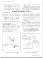
Fluid Checking Procedure ................................................................ ...... 7-30
Fluid Level In d ic a t o r ......................................................................... ...... 7-31
Shift Control Linkage A d ju s tm e n t......................... ............. ................. 7-31
Neutral Safety Switch A d ju s tm e n t......................................................... 7-32
Draining and Refilling Transmission................................................ ...... 7-32
Pressure Regulator Valve .................................................................. ...... 7-33
Control Valve B o d y ........................................................................... ...... 7-33
Governor .................................................................................................... 7-34
Modulator and M odulator V alve ....................................................... ...... 7-34
Parking L in k a g e ...................................................................................
Page
Rear Seal .................................................................................. ..
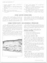
Other Service O perations................................ ...................... ...............
Transmission Replacement ..................................................................
Diagnosis Procedure ..................................
Oil Level and Condition C h e ck .................. ......................................
Manual Linkage ....................... ..........................................................
Case Porosity—R e p a ir......................... ...............................................
Vacuum Modulator Assembly .........................................................
Pressure Switch C h e c k .......................................................................
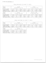
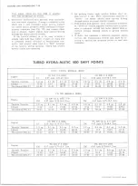
Transmission Shift P o in ts .................................................. ...............
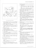
GENERAL DESCRIPTION
The Turbo Hydra-Matic 400 transmission is a fully
automatic unit consisting primarily of a 3-element hy
draulic torque converter and a compound planetary gear
set. Three multiple-disc clutches, one sprag unit, one
roller clutch, and two bands provide the friction elements
required to obtain the desired function of the compound
planetary gear set.
The torque converter couples the engine to the plane
tary gears through oil and provides hydraulic torque
multiplication when required. The compound planetary
gear set produces three forward speeds and reverse.
The 3-element torque converter consists of a pump or
driving member, a turbine or driven member, and a sta
tor assembly. The stator is mounted on a one-way roller
clutch which will allow the stator to turn clockwise but
not counter-clockwise.
The torque converter housing is filled with oil and is
attached to the engine crankshaft by a flex plate and al
ways rotates at engine speed. The converter pump is
an integral part of the converter housing, therefore the
pump blades, rotating at engine speed, set the oil within
the converter into motion and direct it to the turbine,
causing the turbine to rotate.
As the oil passes through the turbine it is traveling in
such a direction that if it were not re-directed by the
stator it would hit the rear of the converter pump blades
and impede its pumping action. So at low turbine speeds,
the oil is re-directed by the stator to the converter pump
in such a manner that it actually assists the converter
pump to deliver power or multiply engine torque.
As turbine speed increases, the direction of the oil
leaving the turbine changes and flows against the rear
side of the stator vanes in a clockwise direction. Since
the stator is now impeding the smooth flow of oil, its
roller clutch releases and it revolves freely on its shaft.
Once the stator becomes inactive, there is no further
multiplication of engine torque within the converter. At
this point, the converter is merely acting as a fluid
coupling as both the converter pump and turbine are being
driven at approximately the same speed - or at one-to-
one ratio.
A hydraulic system pressurized by a gear type pump
provides the working pressure required to operate the
friction elements and automatic controls.
External control connections to transmission are:
Manual Linkage
- To select the desired operating
range.
Engine Vacuum
- To operate a vacuum modula
tor unit.
12 Volt Electrical - To operate an electrical de
tent solenoid.
A vacuum modulator is used to automatically sense any
change in the torque input to the transmission. The vacu
um modulator transmits this signal to the pressure
regulator for line pressure control, to the 1-2 accumu
lator valve, and to the shift valves so that all torque re
quirements of the transmission are met and smooth
shifts are obtained at all throttle openings.
The detent solenoid is activated by an electric switch
on the carburetor. When the throttle is fully opened, the
switch on the carburetor is closed, activating the detent
solenoid and causing the transmission to downshift for
passing speeds.
The selector quadrant has six selector positions: P,
R, N, D, L2, LI.
P. - PARK position positively locks the output shaft to
the transmission case by means of a locking pawl
to prevent the vehicle from rolling in either direc
tion. The engine may be started in Park position.
R. - REVERSE enables the vehicle to be operated in a
reverse direction.
N. - Neutral position enables the engine to be started
and run without driving the vehicle.
D. - DRIVE Range is used for all normal driving condi
tions and maximum economy. Drive Range has
three gear ratios, from the starting ratio to direct
drive. Detent downshifts are available by depress
ing the accelerator to the floor.
L2 - L2 Range has the same starting ratio as Drive
Range, but prevents the transmission from shifting
above second speed to retain second speed accele
ration when extra performance is desired. L2
Range can also be used for engine braking. L2
10-30 CHEVROLET TRUCK SERVICE MANUAL
Содержание 10 1971 Series
Страница 1: ......
Страница 96: ......
Страница 100: ...10 30 CHEVROLET TRUCK SERVICE MANUAL Fig 4 10 30 Series Truck Frame FRAME 2 4 ...
Страница 120: ......
Страница 203: ...ENGINE 6 25 Fig 22L Engine Mounts 10 30 CHEVROLET TRUCK SERVICE MANUAL ...
Страница 215: ...ENGINE 6 37 REAR M O U NT Fig 21V Engine Mounts 10 30 CHEVROLET TRUCK SERVICE MANUAL ...
Страница 218: ......
Страница 249: ......
Страница 250: ...EMISSION CONTROL SYSTEMS 6T 4 Fig 3 Combination Emission Control System Routing V8 10 30 CHEVROLET TRUCK SERVICE MANUAL ...
Страница 324: ......
Страница 339: ...FUEL TANK AND EXHAUST SYSTEMS 8 15 SPECIAL TOOLS Fig 22 Special Tools 1 J 23346 Fuel Tank Gauge Remover and Installer ...
Страница 340: ......
Страница 365: ...10 30 CHEVROLET TRUCK SERVICE MANUAL Fig 43 Power Steering Pump M ounting STEERING 9 25 ...
Страница 368: ......
Страница 386: ......
Страница 390: ...ELECTRICAL BODY AND CHASSIS 12 4 10 30 CHEVROLET TRUCK SERVICE MANUAL ...
Страница 391: ......
Страница 392: ...ELECTRICAL BODY AND CHASSIS 12 6 Fig 5 Rear Lighting Composite 10 30 CHEVROLET TRUCK SERVICE MANUAL ...
Страница 409: ...ELECTRICAL BODY AND CHASSIS 12 23 Fig 27 Engine Compartment CA30 02 10 30 CHEVROLET TRUCK SERVICE MANUAL ...
Страница 410: ...ELECTRICAL BODY AND CHASSIS 12 24 18DK GRN 19 Fig 28 Instrument Panel CA30 02 10 30 CHEVROLET TRUCK SERVICE MANUAL ...
Страница 411: ...ELECTRICAL BODY AND CHASSIS 12 25 Fig 29 Instrument Panel CA30 02 10 30 CHEVROLET TRUCK SERVICE MANUAL ...
Страница 412: ...ELECTRICAL BODY AND CHASSIS 12 26 fh Ar r kk 4 Fig 30 Engine Compartment C A K A 10 20 CA30 03 z _ ...
Страница 416: ...ELECTRICAL BODY AND CHASSIS 12 30 Fig 34 Engine Compartment CA KA10 20 CA30 04 10 30 CHEVROLET TRUCK SERVICE MANUAL ...
Страница 420: ...ELECTRICAL BODY AND CHASSIS 12 34 Fig 38 Engine Compartment C A K A 1 0 20 06 16 10 30 CHEVROLET TRUCK SERVICE MANUAL ...
Страница 422: ...ELECTRICAL BODY AND CHASSIS 12 36 Fig 40 Instrument Panel C A K A 10 20 06 16 10 30 CHEVROLET TRUCK SERVICE MANUAL ...
Страница 423: ...ELECTRICAL BODY AND CHASSIS 12 37 Fig 41 R ear Lamps C A K A 1 0 20 06 16 10 30 CHEVROLET TRUCK SERVICE MANUAL ...
Страница 424: ...ELECTRICAL BODY AND CHASSIS 12 38 Fig 42 Engine Compartment CA KA10 20 CAl30 14 34 10 30 CHEVROLET TRUCK SERVICE MANUAL ...
Страница 426: ...ELECTRICAL BODY AND CHASSIS 12 40 Fig 44 Instrument Panel CA KA10 20 CA30 14 34 10 30 CHEVROLET TRUCK SERVICE MANUAL ...
Страница 428: ......
Страница 432: ......
Страница 449: ...SPECIFICATIONS 9 10 30 CHEVROLET TRUCK SERVICE MANUAL ...
Страница 463: ......
Страница 464: ......
Страница 465: ......
Страница 466: ......