HEATER AND AIR CONDITIONING 1A-26
removal shows no evidence of contamination, replace
a like amount of fresh refrigeration oil into the com
pressor before reinstallation. If it was necessary
to service the entire system because of excessive
contamination in the oil removed, install a full
charge of fresh refrigeration oil in the compressor.
2. Position compressor on the mounting bracket and
install all nuts, bolts and lock washers.
3. Install the connector assembly to the compressor
rear head, using new "O" rings coated with clean
refrigeration oil.
4. Connect the electrical lead to the coil and install
and adjust compressor belt.
5. Evacuate and charge the system.
6. Leak test the system and check for proper operation.
Compressor Belt Tension Adjustment
Adjust the compressor belt to the specifications shown
in the Tune-Up chart in the Engine Specification section
of this manual.
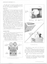
CONDENSER (Fig. 33)
Removal
1. Purge the system of refrigerant.
2. Disconnect the refrigerant lines at the condenser and
cap them.
3. Remove the hood catch assembly.
Remove lower
shroud mounting screws.
4. Remove radiator mounting bolts and push top of radi
ator back enough to make lower condenser mounting
nuts accessible by reaching down between radiator
and radiator support.
5. Remove condenser attaching bolts and remove con
denser (cap the condenser inlet and outlet if it is to
be reused).
Installation
1. Lower the replacement condenser into position and
replace mounting bolts. Be certain shims are in
stalled at lower condenser mount bolts.
Fig. 33 — Condenser and Receiver-Dehydrator
2. Move radiator into place and replace mounting bolts.
Replace shroud lower mounting screws.
3. Replace the hood catch assembly.
4. Connect the refrigerant lines, to the condenser using
new "O" ring seals, coated with clean refrigeration
oil.
5. Add one fluid once of refrigeration oil to the system
if a new condenser was installed. Charge the system
and check performance.
RECEIVER-DEHYDRATOR
The receiver-dehydrator should be replaced if it has
been damaged through an accident or if it leaks or be
comes restricted or clogged. Do not attempt to repair
the receiver-dehydrator.
The receiver-dehydrator is merely a moisture collect
ing device and a refrigerant storage area and is the least
likely component of the system to cause a malfunction.
If at any time when examining the compressor oil,
moisture is found or there is an indication of moisture
at the expansion valve needle, the receiver-dehydrator
should be replaced as follows (fig. 33).
NOTE:
If the receiver-dehydrator is to be re
used, cap the inlet and outlet connections imme
diately. When installing a receiver-dehydrator,
do not uncap the connections until the last possi
ble moment.
Removal
1. Disconnect battery ground cable.
2. Purge the system.
3. Remove the inlet and outlet connections from the
receiver-dehydrator.
4. Remove the receiver-dehydrator mounting bolts and
carefully remove it.
5. Cap the system if the receiver-dehydrator will not
be replaced immediately.
Cap the receiver if it
will be reused.
Installation
1. Place the receiver-dehydrator in position and re
place attaching bolts. Do not uncap the unit until
immediately before connecting lines.
2. Uncap any previously capped connections and con
nect the fittings using new "O" ring seals, coated
with clean refrigeration oil.
3. Evacuate and recharge the system. If a new receiver-
dehydrator was installed, add one fluid ounce refrig
eration oil to the system.
4. Connect battery ground cable.
SIGHT GLASS REPLACEMENT
If damage to the sight glass should occur, a new sight
glass kit should be installed. The kit contains the sight
glass, seal and retainer. (See Figure 34).
1. Purge system.
2. Remove the sight glass retainer nut using a screw
driver and remove old glass and "O" ring seal.
3. Install the new glass and seal and retainer nut, being
careful not to turn the nut past the face of the housing.
To do so may damage the "O" ring seal.
4. Evacuate and recharge the system.
10-30 CHEVROLET TRUCK SERVICE MANUAL
Содержание 10 1971 Series
Страница 1: ......
Страница 96: ......
Страница 100: ...10 30 CHEVROLET TRUCK SERVICE MANUAL Fig 4 10 30 Series Truck Frame FRAME 2 4 ...
Страница 120: ......
Страница 203: ...ENGINE 6 25 Fig 22L Engine Mounts 10 30 CHEVROLET TRUCK SERVICE MANUAL ...
Страница 215: ...ENGINE 6 37 REAR M O U NT Fig 21V Engine Mounts 10 30 CHEVROLET TRUCK SERVICE MANUAL ...
Страница 218: ......
Страница 249: ......
Страница 250: ...EMISSION CONTROL SYSTEMS 6T 4 Fig 3 Combination Emission Control System Routing V8 10 30 CHEVROLET TRUCK SERVICE MANUAL ...
Страница 324: ......
Страница 339: ...FUEL TANK AND EXHAUST SYSTEMS 8 15 SPECIAL TOOLS Fig 22 Special Tools 1 J 23346 Fuel Tank Gauge Remover and Installer ...
Страница 340: ......
Страница 365: ...10 30 CHEVROLET TRUCK SERVICE MANUAL Fig 43 Power Steering Pump M ounting STEERING 9 25 ...
Страница 368: ......
Страница 386: ......
Страница 390: ...ELECTRICAL BODY AND CHASSIS 12 4 10 30 CHEVROLET TRUCK SERVICE MANUAL ...
Страница 391: ......
Страница 392: ...ELECTRICAL BODY AND CHASSIS 12 6 Fig 5 Rear Lighting Composite 10 30 CHEVROLET TRUCK SERVICE MANUAL ...
Страница 409: ...ELECTRICAL BODY AND CHASSIS 12 23 Fig 27 Engine Compartment CA30 02 10 30 CHEVROLET TRUCK SERVICE MANUAL ...
Страница 410: ...ELECTRICAL BODY AND CHASSIS 12 24 18DK GRN 19 Fig 28 Instrument Panel CA30 02 10 30 CHEVROLET TRUCK SERVICE MANUAL ...
Страница 411: ...ELECTRICAL BODY AND CHASSIS 12 25 Fig 29 Instrument Panel CA30 02 10 30 CHEVROLET TRUCK SERVICE MANUAL ...
Страница 412: ...ELECTRICAL BODY AND CHASSIS 12 26 fh Ar r kk 4 Fig 30 Engine Compartment C A K A 10 20 CA30 03 z _ ...
Страница 416: ...ELECTRICAL BODY AND CHASSIS 12 30 Fig 34 Engine Compartment CA KA10 20 CA30 04 10 30 CHEVROLET TRUCK SERVICE MANUAL ...
Страница 420: ...ELECTRICAL BODY AND CHASSIS 12 34 Fig 38 Engine Compartment C A K A 1 0 20 06 16 10 30 CHEVROLET TRUCK SERVICE MANUAL ...
Страница 422: ...ELECTRICAL BODY AND CHASSIS 12 36 Fig 40 Instrument Panel C A K A 10 20 06 16 10 30 CHEVROLET TRUCK SERVICE MANUAL ...
Страница 423: ...ELECTRICAL BODY AND CHASSIS 12 37 Fig 41 R ear Lamps C A K A 1 0 20 06 16 10 30 CHEVROLET TRUCK SERVICE MANUAL ...
Страница 424: ...ELECTRICAL BODY AND CHASSIS 12 38 Fig 42 Engine Compartment CA KA10 20 CAl30 14 34 10 30 CHEVROLET TRUCK SERVICE MANUAL ...
Страница 426: ...ELECTRICAL BODY AND CHASSIS 12 40 Fig 44 Instrument Panel CA KA10 20 CA30 14 34 10 30 CHEVROLET TRUCK SERVICE MANUAL ...
Страница 428: ......
Страница 432: ......
Страница 449: ...SPECIFICATIONS 9 10 30 CHEVROLET TRUCK SERVICE MANUAL ...
Страница 463: ......
Страница 464: ......
Страница 465: ......
Страница 466: ......


