HEATER AND AIR CONDITIONING 1A-22
REFRIGERANT QUICK-CHECK PROCEDURE
The following procedure can be used to quickly de
termine whether or not an air conditioning system
has a proper charge of refrigerant. This check can be
made in a manner of minutes thus facilitating system
diagnosis by pinpointing the problem to the amount of
charge in the system or by eliminating this possibility
from the overall checkout.
Start engine and place on fast idle. Set
controls for maximum cold with blower on high.
Bubbles present in sight No bubbles. Sight glass
glass.
clear.
System low ' on charge.
Check with leak detector.
Correct leak, if any, and
fill system
to proper
charge.
System is
either fully
charged or empty. Feel
high and low pressure
pipes
at
compressor.
High pressure pipe should
be warm; low pressure
pipe should be cold.
I
No appreciable tempera
ture differential noted at
compressor.
I
System empty or nearly
empty. Turn off engine
and connect charging sta
tion. Induce 1/2# of re
frigerant in system (if
system will not accept
charge, start engine and
draw 1/2# in through low
pressure
side).
Check
system with leak detector.
Temperature differential
noted at compressor.
Even though a differential
is noted, there exists a
possibility of overcharge.
An overfilled system will
result in poor cooling dur
ing low speed operation
(as a result of excessive
head pressure). An over
fill is easily checked by
disconnecting the com
pressor clutch connector
while observing the sight
glass.
If refrigerant in sight
glass remains clear for
more than 45 seconds (be
fore foaming and then set
tling away from
sight
glass) an overcharge is
indicated. Verify with a
performance check.
If refrigerant foams and
then settles away from
sight glass in less than 45
seconds, it can be as
sumed that there is a
proper charge of refriger
ant in system.
Continue
checking out system using
performance checks out
lined previously.
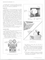
under “ Purging the System.” Refer to Figure 30
while performing the following operation.
2. After system has been purged, connect the vacuum
line to the vacuum pump, turn on pump and open
Vacuum Control Valve (3) - See "General Note"
under "Evacuating and Charging the System." Con
tinue to run pump for 15 minutes after the system
reaches 28-29 inches vacuum.
NOTE:
If 28-29 inches cannot be obtained,
close Vacuum Control Valve (3) and shut off
vacuum pump. Open Refrigerant Control Valve
(4) and allow 1/2 pound of R-12 to enter system.
Locate and repair all leaks.
Purge this 1/2
pound and re-evacuate for 5 minutes.
3. Only after evacuating as above, is system ready for
charging. Note reading on sight glass of charging
cylinder. If it does not contain a sufficient amount
for a full charge, fill to the proper level.
4. With High and Low pressure Valves (1 and 2)
open, close Vacuum Control Valve (3) and open
Refrigerant Control Valve (4).
NOTE:
If the charge will not transfer com
pletely from the station to the system, close
the high pressure valve at the gauge set, set
the air conditioning controls for cooling, check
that the engine compartment is clear of ob
structions, and start the engine. Compressor
operation will decrease the low side pressure
in the system.
System is now charged and should be performance
tested before removing gauges.
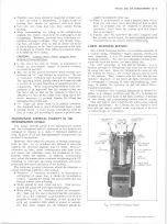
CHECKING OIL
In the six cylinder compressor it is not recommended
that the oil be checked as a matter of course. Generally,
compressor oil level should be checked only where
there is evidence of a major loss of system oil such as
might be caused by:
• A broken refrigerant hose.
• A severe hose fitting leak.
• A very badly leaking compressor seal.
• Collision damage to the system components.
As a quick check on compressor oil charge, with the
engine off, carefully crack open the oil drain plug on the
bottom of the compressor. If oil comes out, the com
pressor has the required amount of oil. To further check
the compressor oil charge, should the above test show
insufficient oil, it is necessary to remove the compressor
from the vehicle, drain and measure the oil.
NOTE:
The oil may appear foamy. This is con
sidered normal.
To further check the compressor oil charge, should the
above test show insufficient oil, it is necessary to remove
the compressor from the vehicle, drain and measure
the oil as outlined under “ Checking Compressor Oil
Charge/'
Checking Compressor Oil Charge
1. Run the system for 10 minutes at 500-600 engine
rpm with controls set for maximum cooling and high
blower speed.
2. Turn off engine, discharge the system, remove
compressor from vehicle, place it in a horizontal
position with the drain plug downward. Remove the
drain plug and, tipping the compressor back and
forth and rotating the compressor shaft, drain the
oil into a clean container, measure and discard the
oil.
3. a. If the quantity drained was 4 fluid oz. or more,
10-30 CHEVROLET TRUCK SERVICE MANUAL
Содержание 10 1971 Series
Страница 1: ......
Страница 96: ......
Страница 100: ...10 30 CHEVROLET TRUCK SERVICE MANUAL Fig 4 10 30 Series Truck Frame FRAME 2 4 ...
Страница 120: ......
Страница 203: ...ENGINE 6 25 Fig 22L Engine Mounts 10 30 CHEVROLET TRUCK SERVICE MANUAL ...
Страница 215: ...ENGINE 6 37 REAR M O U NT Fig 21V Engine Mounts 10 30 CHEVROLET TRUCK SERVICE MANUAL ...
Страница 218: ......
Страница 249: ......
Страница 250: ...EMISSION CONTROL SYSTEMS 6T 4 Fig 3 Combination Emission Control System Routing V8 10 30 CHEVROLET TRUCK SERVICE MANUAL ...
Страница 324: ......
Страница 339: ...FUEL TANK AND EXHAUST SYSTEMS 8 15 SPECIAL TOOLS Fig 22 Special Tools 1 J 23346 Fuel Tank Gauge Remover and Installer ...
Страница 340: ......
Страница 365: ...10 30 CHEVROLET TRUCK SERVICE MANUAL Fig 43 Power Steering Pump M ounting STEERING 9 25 ...
Страница 368: ......
Страница 386: ......
Страница 390: ...ELECTRICAL BODY AND CHASSIS 12 4 10 30 CHEVROLET TRUCK SERVICE MANUAL ...
Страница 391: ......
Страница 392: ...ELECTRICAL BODY AND CHASSIS 12 6 Fig 5 Rear Lighting Composite 10 30 CHEVROLET TRUCK SERVICE MANUAL ...
Страница 409: ...ELECTRICAL BODY AND CHASSIS 12 23 Fig 27 Engine Compartment CA30 02 10 30 CHEVROLET TRUCK SERVICE MANUAL ...
Страница 410: ...ELECTRICAL BODY AND CHASSIS 12 24 18DK GRN 19 Fig 28 Instrument Panel CA30 02 10 30 CHEVROLET TRUCK SERVICE MANUAL ...
Страница 411: ...ELECTRICAL BODY AND CHASSIS 12 25 Fig 29 Instrument Panel CA30 02 10 30 CHEVROLET TRUCK SERVICE MANUAL ...
Страница 412: ...ELECTRICAL BODY AND CHASSIS 12 26 fh Ar r kk 4 Fig 30 Engine Compartment C A K A 10 20 CA30 03 z _ ...
Страница 416: ...ELECTRICAL BODY AND CHASSIS 12 30 Fig 34 Engine Compartment CA KA10 20 CA30 04 10 30 CHEVROLET TRUCK SERVICE MANUAL ...
Страница 420: ...ELECTRICAL BODY AND CHASSIS 12 34 Fig 38 Engine Compartment C A K A 1 0 20 06 16 10 30 CHEVROLET TRUCK SERVICE MANUAL ...
Страница 422: ...ELECTRICAL BODY AND CHASSIS 12 36 Fig 40 Instrument Panel C A K A 10 20 06 16 10 30 CHEVROLET TRUCK SERVICE MANUAL ...
Страница 423: ...ELECTRICAL BODY AND CHASSIS 12 37 Fig 41 R ear Lamps C A K A 1 0 20 06 16 10 30 CHEVROLET TRUCK SERVICE MANUAL ...
Страница 424: ...ELECTRICAL BODY AND CHASSIS 12 38 Fig 42 Engine Compartment CA KA10 20 CAl30 14 34 10 30 CHEVROLET TRUCK SERVICE MANUAL ...
Страница 426: ...ELECTRICAL BODY AND CHASSIS 12 40 Fig 44 Instrument Panel CA KA10 20 CA30 14 34 10 30 CHEVROLET TRUCK SERVICE MANUAL ...
Страница 428: ......
Страница 432: ......
Страница 449: ...SPECIFICATIONS 9 10 30 CHEVROLET TRUCK SERVICE MANUAL ...
Страница 463: ......
Страница 464: ......
Страница 465: ......
Страница 466: ......


