


ENGINE 6-23
Fig. 17L— Checking Timing Gear Backlash
7. If camshaft readings for all lobes are within speci
fications, remove dial indicator assembly.
8. Install and adjust valve mechanism as outlined.
Removal
1. Remove valve lifters as outlined.
2. Remove crankcase front cover as outlined.
3. Remove grille as outlined in Section 13.
4. Remove fuel pump as outlined in Section 6M.
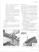
5. Align timing gear marks then remove the two cam
shaft thrust plates screws by working through holes
in the camshaft gear (fig. 15L).
6. Remove the camshaft and gear assembly by pulling
it out through the front of the block.
s-
NOTE:
Support camshaft carefully when re
moving so as not to damage camshaft bearings.
Installation
1. Install the camshaft and gear assembly in the engine
block, being careful not to damage camshaft bearings
or camshaft.
2. Turn crankshaft and camshaft so that the valve tim
ing marks on the gear teeth will line up (fig. 15L).
Push camshaft into position. Install camshaft thrust
plate to block screws and torque to specifications.
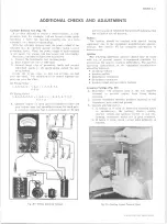
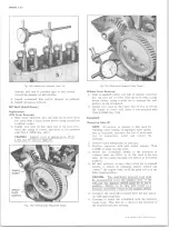
3„ Check camshaft and crankshaft gear run out with a
dial indicator (fig. 16L). The camshaft gear run out
should not exceed <,004" and the crankshaft gear run
out should not exceed .003”.
4. If gear run out is excessive, the gear will have to be
removed and any burrs cleaned from the shaft or
the gear will have to be replaced.
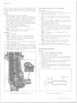
5. Check the backlash between the timing gear teeth
with a dial indicator (fig. 17L). The backlash should
be not less than .004” nor more than .006".
6. Install fuel pump as outlined in Section 6M„
7. Install grille as outlined in Section 13.
8. Install crankcase front cover as outlined.
9. Install valve lifters as outlined.
Timing Gears
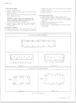
Replacement
With camshaft removed, crankshaft gear may be re
moved using Tool J-8105 (fig. 18L). To install crankshaft
gear use Tool J-5590 (fig. 19L).
For camshaft gear
replacement, refer to “ Camshaft Disassembly” in the
Chassis Overhaul Manual.
Flywheel
Removal
(A ll Except 292
cu.
in. Engines)
1. Remove transmission and/or clutch housing and
clutch from engine.
2. Remove flywheel retaining bolts and r e mo v e
flywheel.
(292 cu. in. Engines)
1. Remove transmission and/or clutch housing and
clutch from engine.
2. Mark relationship of flywheel and crankshaft so that
dowel holes can be aligned in their original positions
on assembly.
3. Remove engine oil pan and rear main bearing cap.
4. Remove flywheel retaining bolts and drive crankshaft
dowels out of flywheel and crankshaft. Rotate crank
shaft as necessary so dowels clear cylinder block.
5. Remove flywheel and discard used dowel pins.
Installation
(A ll Except 292 cu. in. Engines)
1. Clean the mating surfaces of flywheel and crankshaft
to make certain there are no burrs.
2. Install flywheel on crankshaft and position to align
Fig. 1 8 L— Removing Crankshaft G ear
Fig. 19L— Installing Crankshaft G ear
10-30 CHEVROLET TRUCK SERVICE MANUAL
Содержание 10 1971 Series
Страница 1: ......
Страница 96: ......
Страница 100: ...10 30 CHEVROLET TRUCK SERVICE MANUAL Fig 4 10 30 Series Truck Frame FRAME 2 4 ...
Страница 120: ......
Страница 203: ...ENGINE 6 25 Fig 22L Engine Mounts 10 30 CHEVROLET TRUCK SERVICE MANUAL ...
Страница 215: ...ENGINE 6 37 REAR M O U NT Fig 21V Engine Mounts 10 30 CHEVROLET TRUCK SERVICE MANUAL ...
Страница 218: ......
Страница 249: ......
Страница 250: ...EMISSION CONTROL SYSTEMS 6T 4 Fig 3 Combination Emission Control System Routing V8 10 30 CHEVROLET TRUCK SERVICE MANUAL ...
Страница 324: ......
Страница 339: ...FUEL TANK AND EXHAUST SYSTEMS 8 15 SPECIAL TOOLS Fig 22 Special Tools 1 J 23346 Fuel Tank Gauge Remover and Installer ...
Страница 340: ......
Страница 365: ...10 30 CHEVROLET TRUCK SERVICE MANUAL Fig 43 Power Steering Pump M ounting STEERING 9 25 ...
Страница 368: ......
Страница 386: ......
Страница 390: ...ELECTRICAL BODY AND CHASSIS 12 4 10 30 CHEVROLET TRUCK SERVICE MANUAL ...
Страница 391: ......
Страница 392: ...ELECTRICAL BODY AND CHASSIS 12 6 Fig 5 Rear Lighting Composite 10 30 CHEVROLET TRUCK SERVICE MANUAL ...
Страница 409: ...ELECTRICAL BODY AND CHASSIS 12 23 Fig 27 Engine Compartment CA30 02 10 30 CHEVROLET TRUCK SERVICE MANUAL ...
Страница 410: ...ELECTRICAL BODY AND CHASSIS 12 24 18DK GRN 19 Fig 28 Instrument Panel CA30 02 10 30 CHEVROLET TRUCK SERVICE MANUAL ...
Страница 411: ...ELECTRICAL BODY AND CHASSIS 12 25 Fig 29 Instrument Panel CA30 02 10 30 CHEVROLET TRUCK SERVICE MANUAL ...
Страница 412: ...ELECTRICAL BODY AND CHASSIS 12 26 fh Ar r kk 4 Fig 30 Engine Compartment C A K A 10 20 CA30 03 z _ ...
Страница 416: ...ELECTRICAL BODY AND CHASSIS 12 30 Fig 34 Engine Compartment CA KA10 20 CA30 04 10 30 CHEVROLET TRUCK SERVICE MANUAL ...
Страница 420: ...ELECTRICAL BODY AND CHASSIS 12 34 Fig 38 Engine Compartment C A K A 1 0 20 06 16 10 30 CHEVROLET TRUCK SERVICE MANUAL ...
Страница 422: ...ELECTRICAL BODY AND CHASSIS 12 36 Fig 40 Instrument Panel C A K A 10 20 06 16 10 30 CHEVROLET TRUCK SERVICE MANUAL ...
Страница 423: ...ELECTRICAL BODY AND CHASSIS 12 37 Fig 41 R ear Lamps C A K A 1 0 20 06 16 10 30 CHEVROLET TRUCK SERVICE MANUAL ...
Страница 424: ...ELECTRICAL BODY AND CHASSIS 12 38 Fig 42 Engine Compartment CA KA10 20 CAl30 14 34 10 30 CHEVROLET TRUCK SERVICE MANUAL ...
Страница 426: ...ELECTRICAL BODY AND CHASSIS 12 40 Fig 44 Instrument Panel CA KA10 20 CA30 14 34 10 30 CHEVROLET TRUCK SERVICE MANUAL ...
Страница 428: ......
Страница 432: ......
Страница 449: ...SPECIFICATIONS 9 10 30 CHEVROLET TRUCK SERVICE MANUAL ...
Страница 463: ......
Страница 464: ......
Страница 465: ......
Страница 466: ......