HEATER AND AIR CONDITIONING 1A-27
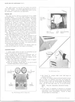
Fig. 34— Sight- Glass Replacement
FOUR-SEASON SYSTEM
BLOWER ASSEMBLY
Removal
1. Disconnect battery ground cable.
2. Support the right front of the hood in the fully raised
position.
3. Carefully scribe the hood and fender locations of the
right hood hinge and remove the hinge.
4. Unclip the blower wire at the blower flange terminal
and note or mark the motor flange position in relation
to the blower case. Disconnect the rubber cooling
tube to the motor.
5. Remove the blower assembly mounting screws.
6. Remove the blower assembly (pry the flange away
from the case carefully in the sealer acts as an
adhesive).
7. Remove the nut attaching the blower wheel to the
motor shaft and separate the assembly.
Installation
1. Assemble the blower wheel to the motor with the
open end of the blower away from the motor.
2. Install the assembly to the blower case, connect
ground strap, and connect the motor wire. Connect
cooling tube to motor.
3. Remount the hood hinge aligning it carefully with the
scribed lines. Check hood alignment.
4. Connect battery ground cable.
EVAPORATOR CORE
Removal
1. Disconnect battery ground cable and purge the
system.
2. Disconnect the evaporator core inlet line at the
expansion valve. Cap the open connections.
3. Disconnect the evaporator oil bleed line at the POA
valve. Cap the open connections.
4. Disconnect the evaporator outlet pipe at the POA
valve. Cap the open connections. Remove the evap
orator outlet pipe clamp.
5. Detach the expansion valve capillary bulb from the
evaporator outlet pipe.
6. Disconnect the vacuum lines at the vacuum reservoir.
7. Remove the screws attaching the inboard case half
to the outboard case half, back up plate, and firewall.
8. Remove inboard case half and evaporator core.
Installation
1. Assemble evaporator core and inboard case half to
the outboard case half. Replace case to case, case
to back up plate, and case to firewall mounting
screws.
2. Attach the vacuum lines to the vacuum reservoir.
3. Mount the expansion valve capillary bulb to the
evaporator core outlet pipe.
4. Connect the evaporator outlet pipe to the POA valve
using a new "O" ring, coated with clean refrigeration
oil. Install the pipe clamp.
5. Connect the evaporator oil bleed line to the POA
valve.
10-30 CHEVROLET TRUCK SERVICE MANUAL
Содержание 10 1971 Series
Страница 1: ......
Страница 96: ......
Страница 100: ...10 30 CHEVROLET TRUCK SERVICE MANUAL Fig 4 10 30 Series Truck Frame FRAME 2 4 ...
Страница 120: ......
Страница 203: ...ENGINE 6 25 Fig 22L Engine Mounts 10 30 CHEVROLET TRUCK SERVICE MANUAL ...
Страница 215: ...ENGINE 6 37 REAR M O U NT Fig 21V Engine Mounts 10 30 CHEVROLET TRUCK SERVICE MANUAL ...
Страница 218: ......
Страница 249: ......
Страница 250: ...EMISSION CONTROL SYSTEMS 6T 4 Fig 3 Combination Emission Control System Routing V8 10 30 CHEVROLET TRUCK SERVICE MANUAL ...
Страница 324: ......
Страница 339: ...FUEL TANK AND EXHAUST SYSTEMS 8 15 SPECIAL TOOLS Fig 22 Special Tools 1 J 23346 Fuel Tank Gauge Remover and Installer ...
Страница 340: ......
Страница 365: ...10 30 CHEVROLET TRUCK SERVICE MANUAL Fig 43 Power Steering Pump M ounting STEERING 9 25 ...
Страница 368: ......
Страница 386: ......
Страница 390: ...ELECTRICAL BODY AND CHASSIS 12 4 10 30 CHEVROLET TRUCK SERVICE MANUAL ...
Страница 391: ......
Страница 392: ...ELECTRICAL BODY AND CHASSIS 12 6 Fig 5 Rear Lighting Composite 10 30 CHEVROLET TRUCK SERVICE MANUAL ...
Страница 409: ...ELECTRICAL BODY AND CHASSIS 12 23 Fig 27 Engine Compartment CA30 02 10 30 CHEVROLET TRUCK SERVICE MANUAL ...
Страница 410: ...ELECTRICAL BODY AND CHASSIS 12 24 18DK GRN 19 Fig 28 Instrument Panel CA30 02 10 30 CHEVROLET TRUCK SERVICE MANUAL ...
Страница 411: ...ELECTRICAL BODY AND CHASSIS 12 25 Fig 29 Instrument Panel CA30 02 10 30 CHEVROLET TRUCK SERVICE MANUAL ...
Страница 412: ...ELECTRICAL BODY AND CHASSIS 12 26 fh Ar r kk 4 Fig 30 Engine Compartment C A K A 10 20 CA30 03 z _ ...
Страница 416: ...ELECTRICAL BODY AND CHASSIS 12 30 Fig 34 Engine Compartment CA KA10 20 CA30 04 10 30 CHEVROLET TRUCK SERVICE MANUAL ...
Страница 420: ...ELECTRICAL BODY AND CHASSIS 12 34 Fig 38 Engine Compartment C A K A 1 0 20 06 16 10 30 CHEVROLET TRUCK SERVICE MANUAL ...
Страница 422: ...ELECTRICAL BODY AND CHASSIS 12 36 Fig 40 Instrument Panel C A K A 10 20 06 16 10 30 CHEVROLET TRUCK SERVICE MANUAL ...
Страница 423: ...ELECTRICAL BODY AND CHASSIS 12 37 Fig 41 R ear Lamps C A K A 1 0 20 06 16 10 30 CHEVROLET TRUCK SERVICE MANUAL ...
Страница 424: ...ELECTRICAL BODY AND CHASSIS 12 38 Fig 42 Engine Compartment CA KA10 20 CAl30 14 34 10 30 CHEVROLET TRUCK SERVICE MANUAL ...
Страница 426: ...ELECTRICAL BODY AND CHASSIS 12 40 Fig 44 Instrument Panel CA KA10 20 CA30 14 34 10 30 CHEVROLET TRUCK SERVICE MANUAL ...
Страница 428: ......
Страница 432: ......
Страница 449: ...SPECIFICATIONS 9 10 30 CHEVROLET TRUCK SERVICE MANUAL ...
Страница 463: ......
Страница 464: ......
Страница 465: ......
Страница 466: ......


